Chapters
Table of Contents

Subscribe to Our Youtube Channel
Related Manuals for Stahl 9496/32 Series


Summary of Contents for Stahl 9496/32 Series
- Page 1 Betriebsanleitung Additional languages r-stahl.com Sockel für CPU und Power Module für Zone 1 Reihe 9496/32...
-
Page 2: Table Of Contents
Inhaltsverzeichnis Inhaltsverzeichnis Allgemeine Angaben....................3 Hersteller......................3 Zu dieser Betriebsanleitung .................3 Weitere Dokumente .....................3 Konformität zu Normen und Bestimmungen ............3 Erläuterung der Symbole ..................4 Symbole in der Betriebsanleitung ................4 Symbole am Gerät ....................4 Sicherheit ......................5 Bestimmungsgemäße Verwendung..............5 Qualifikation des Personals .................5 Restrisiken ......................6 Transport und Lagerung ..................8 Produktauswahl und Projektierung ..............8 Montage und Installation..................9... -
Page 3: Allgemeine Angaben
▶ Betriebsanleitung dem Bedien- und Wartungspersonal jederzeit zugänglich machen. ▶ Betriebsanleitung an jeden folgenden Besitzer oder Benutzer des Geräts weitergeben. ▶ Betriebsanleitung bei jeder von R. STAHL erhaltenen Ergänzung aktualisieren. ID-Nr.: 290163 / 949660310110 Publikationsnummer: 2021-08-05·BA00·III·de·00 Die Originalbetriebsanleitung ist die deutsche Ausgabe. -
Page 4: Erläuterung Der Symbole
Erläuterung der Symbole Erläuterung der Symbole Symbole in der Betriebsanleitung Symbol Bedeutung Hinweis zum leichteren Arbeiten Gefahrensituation, die bei Nichtbeachtung der GEFAHR! Sicherheitsmaßnahmen zum Tod oder zu schweren Verletzungen mit bleibenden Schäden führen kann. Gefahrensituation, die bei Nichtbeachtung der WARNUNG! Sicherheitsmaßnahmen zu schweren Verletzungen führen kann. -
Page 5: Se Fi
Normen und Bestimmungen umfasst. Für Tätigkeiten in explosionsgefährdeten Bereichen sind weitere Kenntnisse erforderlich! R. STAHL empfiehlt einen Kenntnisstand, der in folgenden Normen beschrieben wird: • IEC/EN 60079-14 (Projektierung, Auswahl und Errichtung elektrischer Anlagen) • IEC/EN 60079-17 (Prüfung und Instandhaltung elektrischer Anlagen) •... -
Page 6: Restrisiken
Umgebungsbedingungen (siehe Kapitel "Technische Daten") berücksichtigen. ▶ Gerät nicht belasten. ▶ Verpackung und Gerät auf Beschädigung prüfen. Beschädigungen umgehend an R. STAHL melden. Beschädigtes Gerät nicht in Betrieb nehmen. ▶ Gerät in Originalverpackung, trocken (keine Betauung), in stabiler Lage und sicher vor Erschütterungen lagern. ▶... - Page 7 ▶ Bei eigensicheren und nicht-eigensicheren Stromkreisen einen Abstand von min. 50 mm einhalten. ▶ Reparaturen am Gerät nur durch R. STAHL durchführen lassen. ▶ Gerät nur mit feuchtem Tuch und ohne kratzende, scheuernde oder aggressive Reinigungsmittel oder Lösungen schonend reinigen.
-
Page 8: Produktauswahl Und Projektierung
Transport und Lagerung Transport und Lagerung ▶ Gerät sorgfältig und unter Beachtung der Sicherheitshinweise (siehe Kapitel "Sicherheit") transportieren und lagern. Produktauswahl und Projektierung Bei Neuprojektierung oder Umbau eines Remote I/O Systems IS1+ sind folgende Bedingungen zu berücksichtigen und einzuhalten: Bestückung und zulässige Abmessungen •... -
Page 9: Montage Und Installation
• Der Einsatz einer Montageplatte wird empfohlen. 18688E00 Auf Anfrage ist auch eine Kopfüber-Montage ("upside down") möglich. Rücksprache mit R. STAHL halten! Die Abbildung zeigt beispielhaft den Sockel mit drei Steckplätzen. Die Gebrauchslage gilt ebenso für Sockel mit vier Steckplätzen. - Page 10 Montage und Installation 6.1.2 Montage auf BusRail (DIN-Montageschiene) Eine IP30 Abdeckung für den Sockel 9496 (linke Seite) ist erforderlich, wenn mit der 4-er BusRail 9494 begonnen wird. Bitte beachten: Erst den unbestückten Sockel auf der BusRail befestigen. Vor der Montage der CPU 9442/32 oder des Power Moduls 9445/32 sind die Staubschutzkappen am entsprechenden Steckplatz zu entfernen.
- Page 11 Montage und Installation 20587E00 18451E00 Für Umgebungstemperaturen > 65 °C: ▶ Sockel auf zusätzlicher Montageplatte mit folgender Beschaffenheit befestigen: • Für Umgebungstemperaturen bis +70 °C: Montageplatte aus mindestens 3 mm verzinkten Stahlblech. • Für Umgebungstemperaturen bis +75 °C: Montageplatte aus mindestens 6 mm beschichtetem Aluminium (EN-AW6082 oder vergleichbare Wärmeableitung).
- Page 12 Montage und Installation 6.1.3 Demontage von BusRail (DIN-Montageschiene) GEFAHR! Explosionsgefahr durch Arbeiten am Sockel unter Spannung! Nichtbeachten führt zu tödlichen oder schweren Verletzungen. ▶ Alle angeschlossenen Module und Geräte erst spannungsfrei schalten, bevor der Sockel auf die BusRail gesteckt oder von ihr abgezogen wird. ▶...
-
Page 13: Installation
Montage und Installation 6.1.5 Upgrade auf IS1+ CPU und Power Modul Beim Upgrade von IS1 auf IS1+ Komponenten gemäß folgender Tabelle ersetzen. installiert IS1 Ethernet IS1 RS485 IS1+ Ethernet/RS485 Remote I/O Remote I/O Remote I/O 9441/12 9440/22 9442/32 Power Modul 9444/12 9445/32 Sockel... -
Page 14: Inbetriebnahme
Bei Neueinrichtung das Kommunikationsprotokoll per Drehschalter S1 wie folgt auswählen, siehe Tabelle Kommunikationsprotokoll Drehschalter S1 Drehschalter S1 ab Rev. C Reserved PROFIBUS PNO (Red.) PROFIBUS Stahl Red. Addr. Offs. 1 PROFIBUS Stahl Red. Addr. Offs. 0 PROFINET Reserved Modbus TCP EtherNet/IP Reserved Reserved Reserved –... - Page 15 Inbetriebnahme Für PROFIBUS ohne Redundanz sind alle S1 Schalterstellungen 1 bis 3 mit identischem Verhalten verwendbar. ▶ Bei Upgrade Position des Drehschalters des installierten CPU und Power Moduls bzw. Sockels wie folgt auswählen, siehe Tabelle installiert CPU und Power Modul / Sockel Position Drehschalter S1 9440/22-01-x1-C1243 (DP V1 HART) Pos.
-
Page 16: Instandhaltung, Wartung, Reparatur
▶ Rücksendung bzw. Verpackung der Geräte nur in Absprache mit R. STAHL durchführen! Dazu mit der zuständigen Vertretung von R. STAHL Kontakt aufnehmen. Für die Rücksendung im Reparatur- bzw. Servicefall steht der Kundenservice von R. STAHL zur Verfügung. ▶ Kundenservice persönlich kontaktieren. -
Page 17: Entsorgung
Zubehör und Ersatzteile HINWEIS! Fehlfunktion oder Geräteschaden durch den Einsatz nicht originaler Bauteile. Nichtbeachten kann zu Sachschäden führen. ▶ Nur Original-Zubehör und Original-Ersatzteile der R. STAHL Schaltgeräte GmbH (siehe Datenblatt) verwenden. 290163 / 949660310110 Sockel für CPU und Power Module 2021-08-05·BA00·III·de·00... -
Page 18: Anhang A
Anhang A Anhang A 13.1 Technische Daten Explosionsschutz Global (IECEx) IECEx PTB 17.0026X Ex ia IIC T4 Gb Europa (ATEX) PTB 17 ATEX 2010 X E II 2 G Ex ia IIC T4 Gb Bescheinigungen und Zulassungen Bescheinigungen IECEx, ATEX, EAC (Eurasische Wirtschaftsunion), NEPSI Schiffszertifikate EU RO Mutual Recognition (in Vorbereitung) (inkl. -
Page 19: Cn 13.1 Technische Daten
Technische Daten Einstellungen Kommunikations- Auswahl über Drehschalter S1 protokoll CPU Unterstützte PROFIBUS DP V1 PNO red. HART, PROFIBUS DP V1 STAHL red. HART, Protokolle Modbus TCP, EtherNet/IP, PROFINET Adresseinstellung Drehschalter S2 und S3 (Für PROFIBUS DP und Service Bus) RS485... -
Page 20: Anhang B
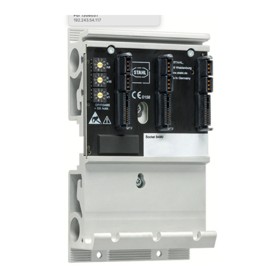
Anhang B Anhang B 14.1 Geräteaufbau Slot 1 Slot 2 Slot 3 Slot 0 Slot 1 Slot 2 Slot 0 18447E00 20589E00 Sockel Typ 9496/32 Sockel Typ 9496/32 mit drei Steckplätzen mit vier Steckplätzen Gerätelement Beschreibung Drehschalter Drehschalter S1 zur Auswahl des Kommunikation Protokoll Drehschalter Drehschalter S2 und S3 zur Einstellung... -
Page 21: 14.2 Maßangaben / Befestigungsmaße
Anhang B 14.2 Maßangaben / Befestigungsmaße Maßzeichnungen (alle Maße in mm [Zoll]) – Änderungen vorbehalten 52 [2,05] 5,50 [0,22] 51 [2,01] 96 [3,78] 13537E00 Sockel Typ 9496/32 mit drei Steckplätzen 290163 / 949660310110 Sockel für CPU und Power Module 2021-08-05·BA00·III·de·00 für Zone 1 Reihe 9496/32... - Page 22 Anhang B Maßzeichnungen (alle Maße in mm [Zoll]) – Änderungen vorbehalten 80 [3,15] 152 [5,98] 52 [2,05] 20590E00 Sockel Typ 9496/32 mit vier Steckplätzen Sockel für CPU und Power Module 290163 / 949660310110 für Zone 1 2021-08-05·BA00·III·de·00 Reihe 9496/32...
- Page 23 Operating instructions Additional languages r-stahl.com Socket for CPU and power modules for Zone 1 Series 9496/32...
- Page 24 Contents Contents General Information .....................3 Manufacturer......................3 About these Operating Instructions..............3 Further Documents ....................3 Conformity with Standards and Regulations............3 Explanation of Symbols ..................4 Symbols used in these Operating Instructions.............4 Symbols on the Device ..................4 Safety........................5 Intended Use......................5 Personnel Qualification ..................5 Residual Risks .....................6 Transport and Storage ..................8 Product Selection and Project Engineering ............8 Mounting and Installation ..................9...
-
Page 25: General Information
Make the operating instructions accessible to operating and maintenance staff at all times. ▶ Pass the operating instructions on to each subsequent owner or user of the device. ▶ Update the operating instructions every time R. STAHL issues an amendment. ID no.: 290163 / 949660310110 Publication code: 2021-08-05·BA00·III·en·00... -
Page 26: Explanation Of Symbols
Explanation of Symbols Explanation of Symbols Symbols used in these Operating Instructions Symbol Meaning Handy hint for making work easier Dangerous situation which can result in fatal or severe injuries DANGER! causing permanent damage if the safety measures are not complied with. -
Page 27: Se Fi
Specialists who perform these activities must have a level of knowledge that meets applicable national standards and regulations. Additional knowledge is required for any activity in hazardous areas! R. STAHL recommends having a level of knowledge equal to that described in the following standards: •... -
Page 28: Residual Risks
▶ Do not place any loads on the device. ▶ Check the packaging and the device for damage. Report any damage to R. STAHL immediately. Do not commission a damaged device. ▶ Store the device in its original packaging in a dry place (with no condensation), and make sure that it is stable and protected against the effects of vibrations and knocks. - Page 29 Maintain a distance of at least 50 mm for intrinsically safe and non-intrinsically safe electrical circuits. ▶ Repair work on the device must be performed only by R. STAHL. ▶ Gently clean the device with a damp cloth only – do not use scratching, abrasive or aggressive cleaning agents or solutions.
-
Page 30: Gr 4 Transport And Storage
Transport and Storage Transport and Storage ▶ Transport and store the device carefully and only in accordance with the safety information (see "Safety" chapter). Product Selection and Project Engineering During new project engineering or modification of a IS1+ Remote I/O system, the following conditions are to be taken into account and adhered to: Equipping and permissible dimensions •... -
Page 31: Mounting And Installation
• Use of a mounting plate is recommended. 18688E00 On request, an upside-down mounting position is also possible. Consult R. STAHL! The figure shows the socket with three slots as an example. The operating position is also valid for the socket with four slots. - Page 32 Mounting and Installation 6.1.2 Mounting on a BusRail (DIN Mounting Rail) An IP30 covering is required for the socket 9496 (left side) if you start with the 4x BusRail 9494. Please observe: First, fasten the unequipped socket to the BusRail. Before mounting the 9442/32 CPU or the 9445/32 power module, the dust caps on the corresponding slot must be removed.
- Page 33 Mounting and Installation 20587E00 18451E00 For ambient temperatures > 65 °C: ▶ Mount the socket on an additional mounting plate with the following properties: • For ambient temperatures up to +70 °C: Mounting plate made of galvanised sheet steel at least 3 mm thick. •...
- Page 34 Mounting and Installation 6.1.3 Dismounting the BusRail (DIN Mounting Rail) DANGER! Explosion hazard due to work on a live socket! Non-compliance results in fatal or severe injuries. ▶ Disconnect all connected modules and devices from the supply before connecting the socket to or disconnecting it from the BusRail. ▶...
-
Page 35: Installation
Mounting and Installation 6.1.5 Upgrading to the IS1+ CPU and Power Module When upgrading from IS1 to IS1+, replace components according to the following table. Installed IS1 Ethernet IS1 RS485 IS1+ Ethernet/RS485 Remote I/O Remote I/O Remote I/O 9441/12 9440/22 9442/32 Power module 9444/12... -
Page 36: Commissioning
During realignment, select the communication protocol for each S1 rotary switch as follows; see the table Communication protocol Rotary switch S1 Rotary switch S1 from rev. C Reserved PROFIBUS PNO (Red.) PROFIBUS Stahl Red. Addr. Offs. 1 PROFIBUS Stahl Red. Addr. Offs. 0 PROFINET Reserved Modbus TCP EtherNet/IP Reserved Reserved Reserved –... - Page 37 Commissioning All S1 switch positions from 1 to 3 with identical behaviour can be used for PROFIBUS without redundancy. ▶ When upgrading, select the position of the rotary switch of the installed CPU and power module or socket as follows; see the table Installed CPU and power module/socket Rotary switch S1 position...
-
Page 38: 8 Maintenance, Overhaul, Repair
Returning the Device ▶ Only return or package the devices after consulting R. STAHL! Contact the responsible representative from R. STAHL. R. STAHL's customer service is available to handle returns if repair or service is required. ▶ Contact customer service personally ▶... -
Page 39: Disposal
NOTICE! Malfunction or damage to the device due to the use of non-original components. Non-compliance can result in material damage. ▶ Use only original accessories and spare parts from R. STAHL Schaltgeräte GmbH (see data sheet). 290163 / 949660310110 Socket for CPU and power modules 2021-08-05·BA00·III·en·00... - Page 40 Appendix A Appendix A 13.1 Technical Data Explosion protection Global (IECEx) IECEx PTB 17.0026X Ex ia IIC T4 Gb Europe (ATEX) PTB 17 ATEX 2010 X E II 2 G Ex ia IIC T4 Gb Certificates and approvals Certificates IECEx, ATEX, EAC (Eurasian Economic Union), NEPSI Ship certificates EU RO Mutual Recognition (in preparation) (incl.
-
Page 41: Cn 13.1 Technical Data
CPU communication Selection using S1 rotary switch protocol Supported protocols PROFIBUS DP V1 PNO red. HART, PROFIBUS DP V1 STAHL red. HART, Modbus TCP, EtherNet/IP, PROFINET Address setting Rotary switches S2 and S3 (for PROFIBUS DP and Service Bus) RS485... -
Page 42: 14.1 Device Design
Appendix B Appendix B 14.1 Device Design Slot 1 Slot 2 Slot 3 Slot 0 Slot 1 Slot 2 Slot 0 18447E00 20589E00 Socket type 9496/32 Socket type 9496/32 with three slots with four slots Device element Description Rotary switch S1 rotary switch for selecting the communication protocol Rotary switch... -
Page 43: 14.2 Dimensions/Fastening Dimensions
Appendix B 14.2 Dimensions/Fastening Dimensions Dimensional drawings (all dimensions in mm [inch]) – Subject to change 52 [2,05] 5,50 [0,22] 51 [2,01] 96 [3,78] 13537E00 Socket type 9496/32 with three slots 290163 / 949660310110 Socket for CPU and power modules 2021-08-05·BA00·III·en·00 for Zone 1 Series 9496/32... - Page 44 Appendix B Dimensional drawings (all dimensions in mm [inch]) – Subject to change 80 [3,15] 152 [5,98] 52 [2,05] 20590E00 Socket type 9496/32 with four slots Socket for CPU and power modules 290163 / 949660310110 for Zone 1 2021-08-05·BA00·III·en·00 Series 9496/32...
Need help?
Do you have a question about the 9496/32 Series and is the answer not in the manual?
Questions and answers