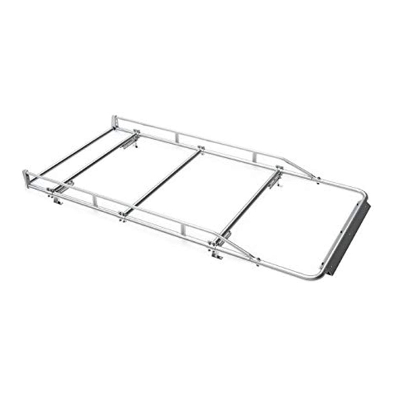
Summary of Contents for Kargo Master 8006A
- Page 1 Instruction Guide 8006A-Rev 1 Kargo Master Rancho Cordova, CA 95742 800-343-7486 CustomerService@KargoMaster.com 20190716R2 DATE: ______________...
-
Page 2: Table Of Contents
Instructions – 8006A-Rev 1 *PLEASE READ ALL INSTRUCTIONS AND WARNINGS PRIOR TO ASSEMBLING, INSTALLING, AND USING THIS PRODUCT* Warning Always check for wires, fuel tanks and lines, brake lines and other important vehicle functionality items prior to drilling and installing all products. -
Page 3: Parts List
Instructions – 8006A-Rev 1 Parts For Technical Support Call: 800-343-7486 Monday-Friday 7AM - 4 PM (PST) Page 3... -
Page 4: Assembly Hardware
Instructions – 8006A-Rev 1 Hardware (18-8006A-M) For Technical Support Call: 800-343-7486 Monday-Friday 7AM - 4 PM (PST) Page 4... - Page 5 Instructions – 8006A-Rev 1 Hardware (18-8006A-M) Continued For Technical Support Call: 800-343-7486 Monday-Friday 7AM - 4 PM (PST) Page 5...
- Page 6 Instructions – 8006A-Rev 1 Hardware (18-8006A-A) For Technical Support Call: 800-343-7486 Monday-Friday 7AM - 4 PM (PST) Page 6...
- Page 7 Instructions – 8006A-Rev 1 Hardware (18-8006A-A) Continued For Technical Support Call: 800-343-7486 Monday-Friday 7AM - 4 PM (PST) Page 7...
- Page 8 Instructions – 8006A-Rev 1 Hardware (18-8006A-C) For Technical Support Call: 800-343-7486 Monday-Friday 7AM - 4 PM (PST) Page 8...
-
Page 9: Step 1A - Transit Connect
Instructions – 8006A-Rev 1 Find vehicle specific feet mounting in the following pages. Step 1A – Transit Connect • Choose the four desired mounting locations from the roof of the van. • Remove the plugs from the roof in ONLY the four desired mounting locations to expose the holes. -
Page 10: Step 1B - Promaster City
Instructions – 8006A-Rev 1 Step 1B – Promaster City • Remove the plugs from the roof in the desired mounting locations to expose the threaded insert. • Place sealant around the exposed holes in the roof under the rubber pieces to prevent water from leaking into the cargo area. -
Page 11: Step 1C - Nv200/City Express
Instructions – 8006A-Rev 1 Step 1C – NV200/City Express • Choose the four desired mounting locations from the roof of the van. • Remove the plugs from the roof in ONLY the four desired mounting locations to expose the holes. -
Page 12: Step 1D - Camper Shell
Instructions – 8006A-Rev 1 Step 1D – Camper shell • Find desired ladder location on top of camper shell. **This step is easier if the rack is completely assembled** • Place feet on top of camper shell in desired location. -
Page 13: Step 2 - Mount Feet To Crossbars
Instructions – 8006A-Rev 1 Step 2 – Mount Crossbars to Feet • Bolt the feet to the crossbar using a 3/8” x 3” hex head bolt, two 3/8” flat washers, a 3/8” x 1-1/2” spacer and a 3/8” nyloc nut in the orientation shown below. -
Page 14: Step 3 - Mount Side Channels
Instructions – 8006A-Rev 1 Step 3 – Mount Side Channels • Place the side channels in the orientation shown. Have the correct side channels on the correct sides. Notice the bend at the rear of each piece. Assembly one side at a time. -
Page 15: Step 5 - Rear Roller Bar
Instructions – 8006A-Rev 1 Step 5 – Rear Roller Bar • Insert the bushing into the end of the rear roller bar. • Stand the side channels upright. • Insert rear roller bar assembly into the holes at the rear of the side channels. -
Page 16: Step 6 - Front Tube
Instructions – 8006A-Rev 1 Step 6 – Front Tube • Place the U-tube to the front of each side channel. • Bolt the U-tube to side channels using 1/2" x 2-1/4” button head cap screw, two 1/2" flat washers and a 1/2" nyloc nut. -
Page 17: Step 7 - Extra Cross Bar
Instructions – 8006A-Rev 1 Step 7 – Extra Cross Bar • Place extra cross bar in desired location. • Place the clamp around the side channel tube. • Align the holes in the clamp with the matching holes on the cross bar. -
Page 18: Step 8 - Wind Deflector
Instructions – 8006A-Rev 1 Step 8 – Wind Deflector • Place the wind deflector around the front tube. • Place the clamp around the front tube and position the clamp so it hooks into the wind deflector. • Attach the clamp to wind deflector using #10 x 1/2"... - Page 19 Instructions – 8006A-Rev 1 GO BACK AND MAKE SURE ALL HARDWARE IS TIGHT START BY TIGHTENING THE FEET TO THE VEHICLE AND MOVING UPWARD AND OUTWARD ON THE RACK YOUR INSTALLATION IS NOW COMPLETE For Technical Support Call: 800-343-7486 Monday-Friday 7AM - 4 PM (PST)


Need help?
Do you have a question about the 8006A and is the answer not in the manual?
Questions and answers