Table of Contents
Advertisement
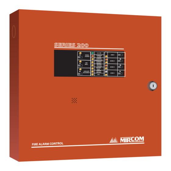
FA-200
Microprocessor-Based Fire Alarm Control Panel
Installation and Operation Manual
SE RI ES 20 0
FIR E AL AR M CO NT RO L
A.C. ON
ZONE 1
SIGNAL
COMMON
SILENCE
ALARM
COMMON
SUPERVISORY
ZONE 2
COMMON
FIRE
TROUBLE
DRILL
BATTERY
TROUBLE
ZONE 3
GROUND
FAULT
REMOTE
AUXILIARY
TROUBLE
DISCONNECT
ZONE 4
TEST
Advanced Life Safety Solutions
LT-636 Rev. 13
July 2006
Advertisement
Table of Contents


Need help?
Do you have a question about the FA-200 Series and is the answer not in the manual?
Questions and answers