Mircom FA-300 Series Installation And Operation Manual
Lcd fire alarm control panel
Hide thumbs
Also See for FA-300 Series:
- Installation and operation manual (106 pages) ,
- User manual (20 pages) ,
- Installation and operation manual (92 pages)
Table of Contents
Advertisement
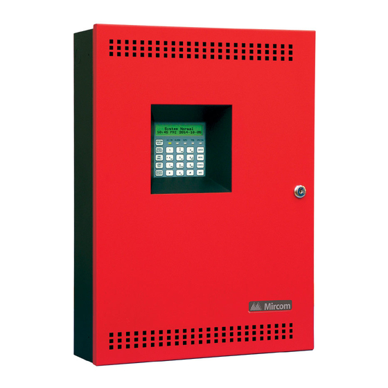
FA-300 Series
LCD Fire Alarm Control Panel
Installation and Operation Manual
Adv ance d Life Safe ty Solu tions
System Normal
10:36AM WED 2003-10-01
A.C. ON ALARM
SUPV
TRBL
CPU FAIL
SYSTEM
RESET
SIGNAL
2
3
ENTER
1
SILENCE
ABC
DEF
FIRE
5
4
6
MENU
DRILL
JKL
MNO
GHI
LAMP
7
8
9
CANCEL
TEST
PQR
STU
WXY
BUZZER
0
*
#
INFO
SILENCE
YZ
Advanced Life Safety Solutions
LT-906 Rev. 9 101106
October 2006
Advertisement
Table of Contents

Related Manuals for Mircom FA-300 Series


Summary of Contents for Mircom FA-300 Series
- Page 1 Advanced Life Safety Solutions FA-300 Series LCD Fire Alarm Control Panel Adv ance d Life Safe ty Solu tions System Normal 10:36AM WED 2003-10-01 A.C. ON ALARM SUPV TRBL CPU FAIL SYSTEM RESET SIGNAL ENTER SILENCE FIRE MENU DRILL LAMP...
- Page 2 Copyrights and Trademarks This manual is copyright 1994 - 2006 by Mircom Technologies Limited. No part of this publication may be reproduced, transmitted, transcribed, stored in a retrieval system, or translated into any language or computer language, in any form by any means electronic, magnetic, optical, chemical, manual, or otherwise without the prior consent of Mircom Technologies Limited.
-
Page 3: Cautions And Warnings
Cautions and Warnings READ AND SAVE THESE INSTRUCTIONS. Follow the instructions in this installation manual. These instructions must be followed to avoid damage to this product and associated equipment. Product operation and reliability depends upon proper installation. DO NOT INSTALL ANY PRODUCT THAT APPEARS DAMAGED. Upon unpacking your equipment, inspect the contents of the carton for shipping damage. -
Page 5: Table Of Contents
FA-300 Series LCD Version Installation and Operation Manual Contents Industry Canada and FCC Notice ................... 1 Introduction ..........................2 Overall Features ........................2 Conventions ..........................3 Circuits ..........................3 Zone............................3 Events ........................... 3 Wiring Styles ......................... 3 System Components ....................... 4 Main Fire Control Panel ...................... - Page 6 Synchronous Strobes......................34 System Sensor’s i3 Devices....................34 Configuration .......................... 36 Entering the Passcode ......................36 Command Menu........................37 1. FA-300 CONFIG (Command-Menu) ................38 2. Config Info (Command-Menu)..................46 3. Set Time (Command-Menu)..................... 47 4. Set Password (Command-Menu)..................48 5.
- Page 7 FA-300 Series LCD Version Installation and Operation Manual List of Figures and Tables Figures Figure 1: Box dimensions, surface mount.................. 8 Figure 2: FA-301-12DDR Box dimensions, semi-flush mounting with trim ring ......9 Figure 2A: FA-300-6DDR/6DR Box dimensions, mounting and trim ring ......... 10 Figure 3: Installation of Adder Modules for FA-301 LCD Panels ..........
- Page 8 List of Figures and Tables...
-
Page 9: Industry Canada And Fcc Notice
Contact your telephone company if you have any questions about your phone line. In the event repairs are ever needed on the Communicator, they should be performed by Mircom Technologies Ltd. or an authorized representative of Mircom Technologies Ltd. For information contact Mircom Technologies Ltd. at the address and phone numbers shown on the back page of this document. -
Page 10: Introduction
Introduction Mircom's FA-300 Series Fire Alarm Control Panel is a Digital Signal Processor (DSP) based fire panel. The FA-300 provides a maximum of 12 supervised Class B or A (Style B or D) Initiating circuits, and maximum of four supervised Class B or A (Style Y or Z) indicating circuits. -
Page 11: Conventions
FA-300 Series LCD Version Installation and Operation Manual Conventions Circuits Refers to an actual electrical interface for Initiating (Detection) and Indicating (Signal) or Relays Zone Is a logical concept for a Fire Alarm Protected Area, and will consist of at least one Circuit. -
Page 12: System Components
System Components System Components Main Fire Control Panel Model Description Twelve-Zone Fire Alarm Control Panel with LCD display and dialer (red door, black box). 12 Class B (Style B) Initiating circuits, and four Power Limited Class B (Style Y) Indicating circuits (up to 1.70 amperes each, 5 amperes total). -
Page 13: Relay Module: 12 Relays
FA-300 Series LCD Version Installation and Operation Manual Relay Module: 12 Relays Model Description RM-312 Twelve-relay adder module RELAY 1 RELAY 2 RELAY 3 RELAY 4 RELAY 5 RELAY 6 RELAY 7 RELAY 8 RELAY 9 RELAY 10 RELAY 11... -
Page 14: Remote Annunciator
DRILL RAM-300LCDR LCD display, red enclosure BUZZER CANCEL SILENCE LAMP INFO TEST Advanced Life Safety Solutions FA-300 SERIES Remote Annunciator Smart Relay Module Model Description Smart Relay Module (12 SRM-312R relays) with red enclosure. Advanced Life Safety Solutions FA-300 SERIES... -
Page 15: Output Class A Converter: Four Circuits
FA-300 Series LCD Version Installation and Operation Manual Output Class A converter: four circuits Model Description Output Class A converter module (four OCAC-304 circuits) Output Class A converter: two circuits Model Description Output Class A converter module (two OCAC-302 circuits) -
Page 16: Mechanical Installation
Mechanical Installation Installing the Enclosure Install the FA-300 Series Fire Alarm Panel enclosure as shown below for the twelve zone models. Mount enclosure surface mount using the four mounting holes, as shown and the screws provided. The backbox may be semi-flush mounted using the trim ring model FA-UNIV-TRB (BLACK), see Figure 2. -
Page 17: Figure 2: Fa-301-12Ddr Box Dimensions, Semi-Flush Mounting With Trim Ring
FA-300 Series LCD Version Installation and Operation Manual Figure 2: FA-301-12DDR Box dimensions, semi-flush mounting with trim ring 11" 1.5" PLACE FA-UNIV-TRB TRIM RING OVER BACKBOX 17" 20.5" 26" Adhere trim ring to 28.5" wall surface around FA-300 backbox. 5.4"... -
Page 18: Figure 2A: Fa-300-6Ddr/6Dr Box Dimensions, Mounting And Trim Ring
Mechanical Installation Figure 2A: FA-300-6DDR/6DR Box dimensions, mounting and trim ring 11" 1.5" PLACE FA-300TRB TRIM RING OVER BACKBOX 17" 4 Mounting Holes for Surface 14.5" Mounting 20.0" Adhere trim ring to wall surface around 22.5" the FA-300 backbox. 5.425" 3.5"... -
Page 19: Installing The Adder Modules
FA-300 Series LCD Version Installation and Operation Manual Installing the Adder Modules FA-300 Series Fire Alarm panels come pre-assembled with all components and boards except for Adder Modules. Module installation locations are shown below. Refer to Figure 4 for Jumper or DIP Switch settings and see Wiring Tables and Information section for wiring information. -
Page 20: Figure 4: Installation Of Adder Modules For Fa-300 Lcd Panels
Mechanical Installation Figure 4: Installation of Adder Modules for FA-300 LCD Panels MAIN FIRE PANEL BOARD CLASS-A converter board for detection circuits ICAC-306 LCD configuration (6 circuits ) tool - CFG-300 plugged into the LCD DISPLAY socket shown. S Y S T E M N O R M A L CLASS-A converter 1 8 : 0 1 M O N 2 0 0 3 - 0 4 - 0 5 board for indicating... -
Page 21: Dip Switch And Jumper Selections For Main Board And Adder Modules
FA-300 Series LCD Version Installation and Operation Manual DIP Switch and Jumper Selections for Main Board and Adder Modules Main Fire Alarm Board Figure 5: Main Fire Alarm Board DIP switch and jumper settings for FA-301 LCD Panels For PC programming use UIMA interface module not UL-864 or ULC-S527 listed. -
Page 22: Figure 6: Main Fire Alarm Board Dip Switch And Jumper Settings For Fa-300 Lcd Panels
DIP Switch and Jumper Selections for Main Board and Adder Modules Figure 6: Main Fire Alarm Board DIP switch and jumper settings for FA-300 LCD Panels For PC programming use UIMA interface module not UL-864 or ULC-S527 listed. Please refer to Document LT-929 for details Telephone line Telephone line... -
Page 23: Icac-306 Input Class-A Converter Adder Module
FA-300 Series LCD Version Installation and Operation Manual ICAC-306 Input Class-A Converter Adder Module Figure 7: ICAC-306 Input Class-A Converter Adder Module ICAC-306 mounting hole for #6-32 screws All these pins comes with red and black wires which are connected to the detection circuit on the main fire alarm board. -
Page 24: Ocac-304/302 Output Class-A Converter Adder Module
DIP Switch and Jumper Selections for Main Board and Adder Modules OCAC-304/302 Output Class-A Converter Adder Module Figure 8: OCAC-304/302 Output Class-A Converter Adder Module mounting hole for mounting hole for #6-32 screws #6-32 screws OCAC-304 OCAC-302 mounting hole for #6-32 screws mounting hole for #6-32 screws... -
Page 25: Rm-306 Six Relay Adder Module
FA-300 Series LCD Version Installation and Operation Manual Programming the relays A typical relay circuit is shown below in Figure 8 with the jumper locations and descriptions. Note: Relay programming should be done before installing the board Figure 10: RM-312/306 Relay programming... -
Page 26: Polarity Reversal And City Tie Module (Model Pr-300)
DIP Switch and Jumper Selections for Main Board and Adder Modules Polarity Reversal and City Tie Module (Model PR-300) Figure 12: Polarity reversal and city tie module Mounting hole for #6-32 screws Mounting hole for #6-32 screws The following hardware configuration must be performed before installing the PR-300 Table 2: PR-300 jumper settings Cable connects to P5 on the Main Fire Alarm Board Cut this jumper for Trouble transmission. -
Page 27: Field Wiring
FA-300 Series LCD Version Installation and Operation Manual Field wiring Main Fire Alarm Board Field Wiring Wire devices to the terminals as shown in the figures that follow. Refer to the Wiring Tables for wire gauges and to Appendix A for specifications. -
Page 28: Figure 14: Initiating Circuit- Class A Or Style D Wiring
Indicating Circuit Wiring The FA-300 Series Fire Alarm supports Class B (Style Y) and Class A (Style Z) wiring for its indicating circuits. Each circuit is supervised by a 3.9K End-of-Line resistor. Each indicating circuit provides up to 1.7 A, 5 A maximum total if no auxiliaries are used. -
Page 29: Figure 16: Indicating Circuit - Class A Or Style Z Wiring
FA-300 Series LCD Version Installation and Operation Manual Figure 16: Indicating circuit – Class A or Style Z wiring OCAC-304 CLASS A CONVERTER MODULE STYLE Y WIRING FIRE ALARM MAIN BOARD INDICATING CIRCUIT 1 INDICATING CIRCUIT #1 INDICATING CIRCUIT #2... -
Page 30: Figure 18: Dialer Wiring
Field wiring Dialer Wiring If you have Fire Alarm Panel Models FA-301-12DDR or FA-300-6DDR there is a dialer on board and terminals marked Line 1 and Line 2 must be wired as shown in Figure 16 below. The dialer circuitry also allows for remote configuration using a PC. -
Page 31: Relay Adder Module Wiring
FA-300 Series LCD Version Installation and Operation Manual Relay Adder Module Wiring Wire relays on the relay adder modules RM-312 and RM-306 as shown in Figures 17 and 18. Figure 19: Relay per zone (RM-312) Terminal connection RM-312 12 RELAY ADDER MODULE... -
Page 32: Polarity Reversal And City Tie Module (Pr-300) Wiring
Field wiring Polarity Reversal and City Tie Module (PR-300) Wiring Wire PR-300 Polarity Reversal and City Tie Module (if used) as shown in Figure 19, below. See Appendix A for module specifications. Power Limited cable type FPL, FPLR or FPLP must be used. For USA installation, the installer must use Atlantic Scientific (Tel: 407-725-8000), Model #24544 Protective Device, or similar UL-Listed QVRG secondary protector, as shown. -
Page 33: Wiring Tables And Information
FA-300 Series LCD Version Installation and Operation Manual Figure 22: Power supply connection J W 1 red red B ATTE RY SEC. TX yellow 240 VAC 50Hz 120 VAC 60Hz green Battery Battery NOTE: TO PREVENT SPARKING, CONNECT BATTERIES AFTER THE SYSTEM MAIN A.C. -
Page 34: Four-Wire Smoke Power (Regulated)
Field wiring Table 4: Indicating Circuit Wiring Maximum wiring run to last device Total Max. loop signal resistance load in 18 AWG 16 AWG 14 AWG 12 AWG in ohms amperes Feet Meters Feet Meters Feet Meters Feet Meters 0.06 2350 3750 1143... -
Page 35: System Checkout
FA-300 Series LCD Version Installation and Operation Manual System Checkout Before turning the power “ON” To prevent sparking, do not connect the batteries. Connect the batteries after powering the system from the main AC supply. 1. Check that all modules are installed in the proper location with the proper connections. -
Page 36: Indicators, Controls And Operations
Indicators, Controls and Operations Indicators, Controls and Operations Refer to Figure 21 below which shows the LCD Display, the Keypad and Control Button locations. Figure 23: LCD Display and control buttons S Y S T E M N O R M A L 1 8 : 0 1 M O N 2 0 0 3 - 0 4 - 0 5 A.C. -
Page 37: Common Indicators
FA-300 Series LCD Version Installation and Operation Manual Common Indicators Buzzer The Buzzer is activated by any of the following events: Fire Alarm: Steady Supervisory Alarm: Fast Flash Trouble: Trouble Flash Rate If the Buzzer is turned ON in response to a Non-Latching Trouble or Supervisory, it will be turned OFF if the condition causing it goes away and there is no other reason for it to be ON. -
Page 38: Common Relays
Indicators, Controls and Operations Signal Silence Button Activation of the Signal Silence button when the panel is in alarm deactivates any Silenceable Indicating Circuits. Non-Silenceable Circuits are unaffected. Signals will resound upon any subsequent alarm. Subsequent operation of signal silence resounds all Silenceable signals. This button does not function during any configured Signal Silence Inhibit Timer period (see Configuration section). -
Page 39: Circuit Types
FA-300 Series LCD Version Installation and Operation Manual Circuit Types Initiating (Detection) Circuit Types Non-Verified Alarm A Non-Verified alarm is a “normal” type of alarm that can have pull stations, smoke detectors, or heat detectors attached to it. Activation of any of these devices will immediately result in an alarm condition in the Fire Alarm Control Panel. -
Page 40: Evacuation Codes
Indicators, Controls and Operations either manually or automatically. While sounding, these devices follow the pattern appropriate for the condition: the configured Evacuation Code (default is Temporal Code) during alarm. Non-Silenceable Signal The Non-Silenceable Signal Circuit is used for audible devices such as bells and piezo mini-horns that may not be silenced either manually or automatically. -
Page 41: Fire Alarm Operation
FA-300 Series LCD Version Installation and Operation Manual Fire Alarm Operation In a basic system set up all alarm inputs are treated in a similar manner. Alarm inputs include any of the following: Non-Verified Alarm, Verified Alarm, Sprinkler Alarm, and Water flow Alarm. If any of these alarm inputs occur when the panel is not already in alarm, the following occurs: •... -
Page 42: Supported Protocols/Devices
Supported Protocols/Devices Synchronous Strobes The synchronous strobe models that are supported by the FA-300 panel include Mircom models FHS-240 and FS-240. A separate compatibility list is available for different supported models. Strobes can be configures as normal (e.g. not synchronized or any of the above; see configuration section). Any selection made is system-wide (e.g. - Page 43 FA-300 Series LCD Version Installation and Operation Manual Open circuit trouble If the loop is broken the panel shows open loop trouble. The panel can still communicate with the devices depending upon where the open occurs. Z o n e - 1 O p e n T r b .
-
Page 44: Configuration
Configuration Configuration There are three methods of configuring the FA-300 LCD Series Fire Alarm Panels: Direct configuration using the main LCD display and the menu buttons. Using a PC or Lap Top Computer with a UIMA converter module. Using a PC or laptop computer with remote connection (must use fire alarm with built-in UDACT). The following information for configuring an FA-300 LCD Series Fire Alarm Panel is based on using the front panel main LCD display for configuration. -
Page 45: Command Menu
FA-300 Series LCD Version Installation and Operation Manual Command Menu The main command menu is pictured below. The first line of the LCD will always show “-Command Menu-“, and the second line scrolls through different selections. Use the “UP” and “DOWN” keys to scroll through the menu, and press the “ENTER”... -
Page 46: Fa-300 Config (Command-Menu)
Configuration 1. FA-300 CONFIG (Command-Menu) The following is a detailed description of the FA-300 configuration menu. -FA-300 Config- 1. Features 2. Inp Zone 3. I3 Zone 4. Opt. Zone 5. Correlation 6. Inp Zone Label 7. Opt Zone Label 8. Default Config Command Menu/FA-300 Config-->Features - Feature Config - 1 Man. - Page 47 FA-300 Series LCD Version Installation and Operation Manual How to Use the Keypad to Program the FA-300 1. Press MENU to enter the command menu. 2. Select a Command Menu option by pressing ENTER. The corresponding submenu will display. 3. Use the up and down arrow buttons to scroll through the submenu.
- Page 48 Configuration Command Menu/FA-300 Config/Features/ [X] DISABLE->Default 6.Signal-Silence Inhibit timer Use this function to inhibit the [ ] 10 SEC “SIGNAL SILENCE” switch for a [ ] 20 SEC desired length of time. This time S i g - S i l . I n h i b i t T m r [ ] 30 SEC period should expire before the signals may be silenced.
- Page 49 FA-300 Series LCD Version Installation and Operation Manual Command Menu/FA-300 Config/Features/ 13.Signal Isolators Enable this function only when [ ] ENABLE suite isolators are used (Canada S i g - S i l . I s o l a t o r [X] DISABLE ->Def...
- Page 50 Configuration Command Menu-->FA-300 Config Note: Refer to How to Use the Keypad to Program the FA-300 on page 39 for detailed instructions on making menu selections. Inp Zone I n i t i a t i n g Z o n e 1 Z o n e - 1 2 Z o n e - 2 1 2 Z o n e 1 2...
- Page 51 FA-300 Series LCD Version Installation and Operation Manual Command Menu-->FA-300 Config Note: Refer to How to Use the Keypad to Program the FA-300 on page 39 for detailed instructions on making menu selections. Opt Zone I n d i c a t i n g Z o n e...
- Page 52 Configuration Command Menu-->FA-300 Config Note: Refer to How to Use the Keypad to Program the FA-300 on page 39 for detailed instructions on making menu selections. Inp Zone Label I n i t i a t i n g Z o n e 1 Z o n e - 1 2 Z o n e - 2 1 2 Z o n e 1 2...
- Page 53 FA-300 Series LCD Version Installation and Operation Manual Command Menu-->FA-300 Config Note: Refer to How to Use the Keypad to Program the FA-300 on page 39 for detailed instructions on making menu selections. Opt Zone Label I n d i c a t i n g Z o n e...
-
Page 54: Config Info (Command-Menu)
Configuration 2. Config Info (Command-Menu) Note: Refer to How to Use the Keypad to Program the FA-300 on page 39 for detailed instructions on making menu selections. Configuration type will show how the panel was configured. Configuration type: “Factory default” means the panel has not been configured, it is as it came from the factory. -
Page 55: Set Time (Command-Menu)
FA-300 Series LCD Version Installation and Operation Manual 3. Set Time (Command-Menu) 1 Daylight Save 2 Time Clock 3 Compensation Note: Refer to How to Use the Keypad to Program the FA-300 on page 39 for detailed instructions on making menu selections. -
Page 56: Set Password (Command-Menu)
Configuration 4. Set Password (Command-Menu) Note: Refer to How to Use the Keypad to Program the FA-300 on page 39 for detailed instructions on making menu selections. Enter new passcode Re-enter passcode If the passcode does not match, the Use this function to change the following message appears and the passcode. -
Page 57: Clear Event Log (Command-Menu)
FA-300 Series LCD Version Installation and Operation Manual 6. Clear Event Log (Command-Menu) Note: Refer to How to Use the Keypad to Program the FA-300 on page 39 for detailed instructions on making menu selections. -Select Log- 1 Alarm Log... -
Page 58: Walk Test (Command-Menu)
Configuration 7. Walk Test (Command-Menu) Note: Refer to How to Use the Keypad to Program the FA-300 on page 39 for detailed instructions on making menu selections. Walk-Test allows an installer to verify the initiating circuit wiring in a system. When walk test is selected, the following screen confirms the operation: P e r f o r m t h e w a l k t e s t ? Y... -
Page 59: I3 Loop Test (Command-Menu)
FA-300 Series LCD Version Installation and Operation Manual 8. i Loop Test (Command-Menu) Note: Refer to How to Use the Keypad to Program the FA-300 on page 39 for detailed instructions on making menu selections. The i maintenance test is designed to test the devices on the i zone. -
Page 60: Dialer Config (Command-Menu)
Configuration 9. Dialer Config (Command-Menu) Note: Refer to How to Use the Keypad to Program the FA-300 on page 39 for detailed instructions on making menu selections. The following illustration shows the dialer configuration menu. Each item in this menu is described below in detail. -Dialer Config - 1 Account Info 2 Telephone line... - Page 61 FA-300 Series LCD Version Installation and Operation Manual Command Menu/Dialer Config/Account Info Use this function to set the telephone number of the monitoring station. The 2.Account#1 Telephone Number maximum # of digits allowed is 19 including “,” and numerals. The “,”...
- Page 62 Configuration Command Menu-->Dialer Config Note: Refer to How to Use the Keypad to Program the FA-300 on page 39 for detailed instructions on making menu selections. Telephone Line - T e l e p h o n e L i n e - 1 L i n e 1 D i a l t y p e 2 L i n e 2 D i a l t y p e 3 L i n e 1 D i a l t o n e...
- Page 63 FA-300 Series LCD Version Installation and Operation Manual Command Menu-->Dialer-Config Note: Refer to How to Use the Keypad to Program the FA-300 on page 39 for detailed instructions on making menu selections. Report Options - Report Options - 1 Alarm Prio.
- Page 64 Configuration Command Menu/Dialer-Config/Report Options Use this function to select the functionality of the dialer. In 6.Dialer operation mode DACT mode only common [X] (U)DACT ->Default trouble/alarm/supervisory are D i a l e r O p e r . M o d e : [ ] DACT reported while in UDACT mode all point information is...
-
Page 65: Test Dialer (Command-Menu)
FA-300 Series LCD Version Installation and Operation Manual Command Menu-->Dialer-Config Note: Refer to How to Use the Keypad to Program the FA-300 on page 39 for detailed instructions on making menu selections. Dialer Enable/Disable D i a l e r E n a / D i s The dialer is enabled by default. - Page 66 Configuration Dialer Test Messages The following messages will display during the test processes of Lines #1 and #2. The messages that will appear depend on the status of the dialer and the test results that are found. The dialer is checking the line for voltage. This Dialer idle now message automatically displays when Maual Test is selected.
-
Page 67: Bypass Det Ckt (Command-Menu)
FA-300 Series LCD Version Installation and Operation Manual 11. Bypass Det Ckt (Command-Menu) Note: Refer to How to Use the Keypad to Program the FA-300 on page 39 for detailed instructions on making menu selections. Initiating zones may be bypassed individually. -
Page 68: Exit (Command-Menu)
Configuration 14. Exit (Command-Menu) Note: Refer to How to Use the Keypad to Program the FA-300 on page 39 for detailed instructions on making menu selections. Pressing “ENTER” after selecting “Exit” from the main menu will return the panel to normal LCD operation. Zone messages Point annunciation is indicated on the LCD display. -
Page 69: Battery Trouble
FA-300 Series LCD Version Installation and Operation Manual AC Power Fail The AC power fail trouble is generated when the power drops below the UL specified value. The trouble is restored when the power returns to the normal value. T ro u b le c o d e... - Page 70 Configuration Remote Annunciator Troubles related to the annunciator can have two possibilities: either the main panel and annunciator failed to communicate with each other, or an unconfigured remote annunciator is responding to the main panel. In both the cases, the following trouble message is displayed: T ro u b le in fo T ro u b le T yp e T ro u b le c o d e...
- Page 71 FA-300 Series LCD Version Installation and Operation Manual Supervised auxiliary supply The supervised auxiliary supply is supervised for shorts. When a short is detected on supervised aux supply the power is cut off and a trouble message is generated. Press the system “RESET” key to restore power to the system.
- Page 72 Configuration If there is an open detected on the city tie output, the following trouble message is displayed: T ro u b le c o d e T ro u b le In fo T ro u b le T yp e C i t y T i e t r o u b l e T r b : 0 x 0 3 I n f o : 0 x 0 0 0 1 "IN F O "...
-
Page 73: Appendix A: Compatible Receivers
FA-300 Series LCD Version Installation and Operation Manual Appendix A: Compatible Receivers The dialers that are built into select models of the FA-300 Series Fire Alarm Control Panels are compatible with the following Digital Alarm Communicator Receivers (DACR): DACR Receiver Model... -
Page 74: Appendix B: Reporting
Appendix B: Reporting Appendix B: Reporting Ademco Contact-ID FA-300 Event Codes Event Description Event Family Qualifier Code Group # Contact # Phone Line #1 trouble detected Trouble New event 1 351 Phone Line #2 trouble detected Trouble New event 1 352 Phone Line #1 trouble restored Trouble Restore... -
Page 75: Security Industries Association Sia-Dcs
FA-300 Series LCD Version Installation and Operation Manual Security Industries Association SIA-DCS SIA protocol does not define indicating zone troubles, but lists it as Untyped Zone Trouble/Restore. FA-300 Event Codes SIA Event Event Description Event Family Qualifier Parameter Code Phone Line #1 trouble detected... -
Page 76: Appendix C: Specifications
PR-300 Polarity reversal city tie module (optional) RM-312/306 Relay Module (optional) System Model: FA-300 Series LCD Version Fire Alarm Control Panel System Type: Local, Auxiliary (using PR-300), Remote Protected Premise Station (using PR-300 or FA-301-12DDR or FA-300-6DDR) Central Station Protected Premises (using FA-301-12DDR or... -
Page 77: Appendix D: Power Supply And Battery Calculations (Selection Guide)
([STANDBY (A) ______ ] X [(24 or 60 Hours) ___ ]) + ([ALARM (B) ______ ] X [ ' Alarm in Hr.] _____) = (C) ______AH Total Alarm Current: Must be 6 amperes or less for FA-300 Series. Indicating Circuits must not exceed 5 amperes. -
Page 78: Warranty
Warranty & Warning Information Warranty & Warning Information Warning Please Read Carefully Note to End Users: This equipment is subject to terms and conditions of sale as follows: Note to Installers This warning contains vital information. As the only individual in contact with system users, it is your responsibility to bring each item in this warning to the attention of the users of this system. - Page 79 Mircom shall not be liable for any delays, breakdowns, interruptions, loss, destruction, alteration or other problems in the use of a product arising our of, or caused by, the software.
-
Page 80: Limited Warranty
(90) days, whichever is longer. The original owner must promptly notify Mircom Technologies Ltd. in writing that there is defect in material or workmanship, such written notice to be received in all events prior to expiration of the warranty period. -
Page 81: Out Of Warranty Repairs
Products which Mircom Technologies Ltd. determines to be repairable will be repaired and returned. A set fee which Mircom Technologies Ltd. has predetermined and which may be revised from time to time, will be charged for each unit repaired. - Page 82 Notes...
- Page 84 Advanced Life Safety Solutions Canada U.S.A. © Mircom 2006 Printed in Canada 25 Interchange Way 60 Industrial Parkway PMB 278 Subject to change without prior notice Vaughan, ON L4K 5W3 Cheektowaga, NY 14227 Tel: 1-888-660-4655 Fax: 1-888-660-4113 www.mircom.com Tel: 905-660-4655 Fax: 905-660-4113...
Need help?
Do you have a question about the FA-300 Series and is the answer not in the manual?
Questions and answers