
Related Manuals for Mircom FA-300-6L Series


Summary of Contents for Mircom FA-300-6L Series
- Page 1 Advanced Life Safety Solutions FA-300-6L Series LED Fire Alarm Control Panel Adva nced Life Safe ty Solu tions WALK TEST Installation and Operation Manual LT-950 Rev. 4 February 2007...
-
Page 3: Table Of Contents
FA-300-6L Installation and Operation Manual Table of Contents Industry Canada and FCC Notice ................... 1 Introduction ..........................2 Overall Features ........................2 Conventions ..........................3 Circuits ..........................3 Zone............................3 Display Points ........................3 Wiring Styles ......................... 3 System Components ....................... 4 Main Fire Control Panel ...................... - Page 4 Table of Contents Single Stage Operation ......................29 Supported Protocols/Devices ....................30 Synchronous Strobes......................30 System Sensor’s i3 Devices....................30 Configuration and CFG-300 LCD Service Tool ..............32 Entering the Passcode ......................33 Command Menu........................33 How to Use the Keypad to Program the FA-300..............34 1.
- Page 5 FA-300-6L Installation and Operation Manual List of Figures & Tables Figure 1: Box dimensions, surface mount................7 Figure 2: Installation of Adder Modules ................8 Figure 3: Main Fire Alarm Board cable connector and jumper settings ....... 9 Figure 4: ICAC-306 Input Class-A Converter Adder Module ..........10 Figure 5: OCAC-302 Output Class-A Converter Adder Module ...........
- Page 6 List of Figures & Tables...
-
Page 7: Industry Canada And Fcc Notice
Contact your telephone company if you have any questions about your phone line. In the event repairs are ever needed on the Communicator, they should be performed by Mircom Technologies Ltd. or an authorized representative of Mircom Technologies Ltd. For information contact Mircom Technologies Ltd. at the address and phone numbers shown on the back page of this document. -
Page 8: Introduction
Introduction Mircom's FA-300 Series Fire Alarm Control Panel is a Digital Signal Processor (DSP)-based fire panel. The FA- 300 provides six supervised Class B or A (Style B or D) Initiating circuits, and four supervised Class B or A (Style Y or Z) indicating circuits. -
Page 9: Conventions
FA-300-6L Installation and Operation Manual Conventions Circuits Refers to an actual electrical interface for Initiating (Detection) and Indicating (Signal) or Relays. Zone Is a logical concept for a Fire Alarm Protected Area, and will consist of at least one Circuit. Often the terms Zone and Circuit are used interchangeably, but in this Manual the term Circuit is used. -
Page 10: System Components
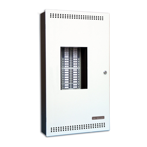
System Components System Components Main Fire Control Panel Model Description 6 Zone Fire Alarm Control Panel with LED display (white door, black box). 6 Class B (Style B) Initiating circuits, and two Power Limited Class B (Style Y) Indicating circuits (up to 1.70 amperes each, 5 amperes total). -
Page 11: Remote Annunciator
FA-300-6L Installation and Operation Manual Remote Annunciator Model Description Remote Annunciator RAM-300LCDW module, LCD display, S Y S T E M N O R M A L white painted box 1 8 : 0 1 M O N 2 0 0 3 - 0 4 - 0 5 A.C. -
Page 12: Input Class A Converter: Six Circuits
System Components Input Class A converter: Six Circuits Model Description Input Class A converter Module (six circuits). This module has ICAC-306 built in Active End-of-Line resistors. Output Class A converter: two circuits Model Description Output Class A converter module (two OCAC-302 circuits) Active end-of-line... -
Page 13: Mechanical Installation
FA-300-6L Installation and Operation Manual Mechanical Installation Installing the Enclosure Install the FA-300 Series Fire Alarm Panel enclosure as shown below. Mount enclosure surface mount using the four mounting holes, as shown and the screws provided. Figure 1: Box dimensions, surface mount 11"... -
Page 14: Installing The Adder Modules
Mechanical Installation Installing the Adder Modules FA-300 Series Fire Alarm panels come pre-assembled with all components and boards except for Adder Modules. Module installation locations are shown below. Refer to Figure 3 on the next page for Jumper or DIP Switch settings and see Wiring Tables and Information for wiring specifications. -
Page 15: Cable And Jumper Connections For Main Board And Adder Modules
FA-300-6L Installation and Operation Manual Cable and Jumper Connections for Main Board and Adder Modules Main Fire Alarm Board Figure 3: Main Fire Alarm Board cable connector and jumper settings JW3-Removed all the time For front panel programming use CFG -300 configuration tool not UL-864 or ULC-S527 listed. -
Page 16: Icac-306 Input Class-A Converter Adder Module
Cable and Jumper Connections for Main Board and Adder Modules Table 1: Connectors and Jumpers on the Main Fire Alarm Board Remove this jumper if PR-300 is connected. Cable from connector P1 of the RM-306 Relay Adder Module connects here. Otherwise not used. -
Page 17: Ocac-302 Output Class-A Converter Adder Module
FA-300-6L Installation and Operation Manual OCAC-302 Output Class-A Converter Adder Module Figure 5: OCAC-302 Output Class-A Converter Adder Module mounting hole for #6-32 screws mounting hole for #6-32 screws OCAC-304 OCAC-302 mounting hole for #6-32 screws mounting hole for #6-32 screws Indicating circuits must be wired from the OCAC-302 to the main Fire Alarm board. -
Page 18: Figure 7: Rm-306 Relay Programming
Cable and Jumper Connections for Main Board and Adder Modules Figure 7: RM-306 Relay programming ZONE JUMPER installed: turns ON relay when the zone (1) is active LOGICAL OR WITH ADJACENT ZONE removed: does not turn ON the relay when jumper installed: this relay 1 works in zone (1) is active conjunction with relay 2... -
Page 19: Field Wiring
FA-300-6L Installation and Operation Manual Field wiring Main Fire Alarm Board Field Wiring Wire devices to the terminals as shown in the figures that follow. Refer to the Wiring Tables on page 19 for wire gauges. CAUTION: Do not exceed power supply ratings. Initiating Circuit Wiring Wiring diagrams for the initiating circuits are shown below. -
Page 20: Figure 10: Initiating Circuit– Class A Or Style D Wiring
Field wiring Figure 10: Initiating circuit– Class A or Style D wiring DCAC-306 CLASS A ICAC CONVERTER MODULE STYLE D WIRING FIRE ALARM MAIN BOARD INITIATING CIRCUIT - 1 ALARM ZONE INITIATING CIRCUIT #1 INITIATING STYLE D CIRCUIT #2 WIRING INITIATING CIRCUIT - 2 4 MORE INITIATING... -
Page 21: Figure 13: Four-Wire Smoke Detector Wiring
FA-300-6L Installation and Operation Manual Figure 12: Indicating circuit –Class A or Style Z wiring OCAC-304 CLASS A CONVERTER MODULE STYLE Z WIRING FIRE ALARM MAIN BOARD INDICATING CIRCUIT 1 INDICATING CIRCUIT #1 INDICATING CIRCUIT #2 STYLE Z WIRING INDICATING CIRCUIT 2 BELL STROBE... -
Page 22: Relay Adder Module Wiring
Field wiring Dialer Wiring If you have Fire Alarm Panel Model FA-300-6LD there is a dialer on board and terminals marked Line 1 and Line 2 must be wired as shown in Figure 14 below. Figure 14: Dialer wiring FIRE ALARM MAIN BOARD RJ31X GREEN... -
Page 23: Polarity Reversal And City Tie Module (Pr-300) Wiring
FA-300-6L Installation and Operation Manual Polarity Reversal and City Tie Module (PR-300) Wiring Wire PR-300 Polarity Reversal and City Tie Module (if used) as shown in Figure 16, below. Power Limited cable type FPL, FPLR or FPLP must be used. For USA installation, the installer must use Atlantic Scientific (Tel: 407-725-8000), Model #24544 Protective Device, or similar UL-Listed QVRG secondary protector, as shown. -
Page 24: Power Supply Connection
Field wiring Power supply connection The power supply is part of the Main Chassis. The ratings are: Type Rating 120VAC, 60Hz, 1.7A / 240VAC, 50Hz, 85A, 10A slow Electrical Input rating blow fuse on secondary of transformer Power supply total current 6.35A maximum at secondary of transformer Battery fuse on Main 10A, slow blow micro fuse... -
Page 25: Wiring Tables And Information
FA-300-6L Installation and Operation Manual Wiring Tables and Information Table 3: Initiating Circuit Wiring Wire gauge Maximum wiring run to last device Notes: Feet Meters • For Class A the maximum wiring run to the last device is 2990 divided by two. 4760 1450 •... -
Page 26: System Checkout
System Checkout System Checkout Before turning the power “ON” To prevent sparking, do not connect the batteries. Connect the batteries after powering the system from the main AC supply. 1. Check that all modules are installed in the proper location with the proper connections. 2. -
Page 27: Indicators, Controls And Operations
• Trouble Flash (Trouble)- 20 flashes per minute, 50% duty cycle Note that each display is supplied with laser printer printable paper labels for sliding into the plastic label template on the panel. For the Main Display, the paper label is Mircom# NP-2057; this includes English and French versions. -
Page 28: Common Indicators
Indicators, Controls and Operations Common Indicators Buzzer The Buzzer is activated by any of the following events: Fire Alarm: Steady Supervisory Alarm: Fast Flash Trouble: Trouble Flash Rate If the Buzzer is turned on in response to a Non-Latching Trouble or Supervisory, it will be turned off if the condition causing it goes away and there is no other reason for it to be on. -
Page 29: Alarm Circuit Indicators
FA-300-6L Installation and Operation Manual Signal Silence LED The Signal Silence indicator flashes amber, at the trouble rate, when indication Circuits are Silenced either by the Signal Silence button, or by the Auto Signal Silence Timer. It is turned off when the Signals are re-sounded by a subsequent Alarm. -
Page 30: Monitor Circuit Indicators
Indicators, Controls and Operations Monitor Circuit Indicators This operation applies to initiating circuits configured as monitor circuits. The following table summarizes the indications in response to different events. Event Circuit Trouble LED Configuration Flashes at the trouble rate Open circuit or (Style D)/(Class A) trouble (amber) Flashes at the trouble rate Monitor... -
Page 31: Common Controls
FA-300-6L Installation and Operation Manual Common Controls Menu Buttons To use the menu buttons you will need to install the CFG-300 configuration tool. See Configuration and CFG-300 Tool on page 32 for details. Menu Button Pressing and entering the passcode will allow you to enter the command menu. Info Button When the system is off-normal, press to display extra information of the event. -
Page 32: Circuit (Zone) Disconnect Buttons
Indicators, Controls and Operations Lamp Test Button Activation of the Lamp Test button causes all front panel Indicators to steadily illuminate and turns the buzzer ON steady. If Lamp Test is active for more than 10 seconds, Common Trouble is activated. The lamp test for CPU Fail LED is during power up. -
Page 33: Circuit Types
FA-300-6L Installation and Operation Manual Auxiliary Alarm Relay The Auxiliary Alarm Relay functions the same way as the Common Alarm Relay in every respect except that it can be disconnected by auxiliary disconnect with or without other correlated relays if it is programmed to do so (see Configuration section). -
Page 34: Evacuation Codes
Indicators, Controls and Operations Monitor This is a supervised general-purpose non-latching input used mainly for correlating to a relay circuit. No other system condition occurs as a result of its activation (short-circuit), although it is supervised for Trouble (open-circuit). Trouble-Only The Trouble-Only circuit monitors a Trouble Condition from an external device such as QX-5000 Audio System. -
Page 35: Single Stage Operation
FA-300-6L Installation and Operation Manual Figure 19: Evacuation and Alert Codes C O N T IN O U S T E M P O R A L C O D E 0.5s 1.5s M A R C H C O D E 0.5s C A L IF O R N IA C O D E A L E R T C O D E... -
Page 36: Supported Protocols/Devices
Supported Protocols/Devices Synchronous Strobes The synchronous strobe models that are supported by the FA-300 panel include Mircom models FHS-240 and FS- 240. A separate compatibility list is available for different supported models (LT-1007). Strobes can be configured as normal (e.g. not synchronized or any of the above; see configuration section). Any selection made is system-wide (e.g. - Page 37 FA-300-6L Installation and Operation Manual Open circuit trouble If the loop is broken the panel shows open loop trouble. The panel can still communicate with the devices depending upon where the open occurs. Z o n e - 1 T r o u b l e O p e n 1 / 1 Communication Trouble If there is a fault in the line or the line is too noisy, the panel cannot communicate with the devices.
-
Page 38: Configuration And Cfg-300 Lcd Service Tool
Configuration and CFG-300 LCD Service Tool Configuration and CFG-300 LCD Service Tool There are three methods of configuring the FA-300 LED Series Fire Alarm Panels: 1. Using the CFG-300 LCD Tool (see further documentation packaged with CFG-300 for configuration informa- tion). -
Page 39: Entering The Passcode
FA-300-6L Installation and Operation Manual Entering the Passcode The programming section is passcode protected. The following screen shows the message that is displayed to enter the passcode. The maximum allowable passcode is ten digits long, and permits numerical values only. Press (Enter button) key after entering the passcode. -
Page 40: How To Use The Keypad To Program The Fa-300
Configuration and CFG-300 LCD Service Tool Pressing “LAMP TEST” at any time will show the information about the system and the software version as shown below. FA-300-6LD wUDACT Version 0.0.4 The first line shows the model number and panel type and the second line shows the software version number. The version of the software is read as Major.Minor.Revision. - Page 41 FA-300-6L Installation and Operation Manual Command Menu/Panel Config-->Features -Feature Config- 1. Man. Sig. Sil 2. Fire Drill 3. Opt. Ckt. Corr 4. Wtr/Sprk. Retd 5. Aux Dis Corr 6. Sig-Sil Inh Tm 7.Aux Dis, Alm&Sup 8. Auto Sil. Tmr 9. Rem. Annun. 10.
- Page 42 Configuration and CFG-300 LCD Service Tool Command Menu/Panel Config/Features/ If disabled, whatever correlation 3.Output Circuit Correlation [X] DISABLE->Default is set in the correlation section [ ] ENABLE is effective. If enabled, all the O p t . C k t . C o r r . output circuits are correlated to all the input circuits.
- Page 43 The [X] NORMAL ->Default selection is system-wide and S t r o b e T y p e [ ] MIRCOM applies to all indicating circuits [ X ] N O R M A L [ ] FARADY configured as strobes.
- Page 44 Configuration and CFG-300 LCD Service Tool Command Menu/Panel Config/Features/ Enable this function if using an 16. Active EOL Active EOL. If ICAC-306 is [X] DISABLE->Default used, this function should be Active EOL enabled since the Class A [ ] NO Converter has built in Active [X] DISABLE EOL resistors.
- Page 45 FA-300-6L Installation and Operation Manual Command Menu-->Panel Config Note: Refer to How to Use the Keypad to Program the FA-300 on page 34 for detailed instructions on making menu selections. i3 Zones This i3 Zones menu is used to program the process type for the initiating circuits. Select the zone to be an i3 zone, otherwise the panel will treat the zone as a normal detection zone.
- Page 46 Configuration and CFG-300 LCD Service Tool Command Menu-->Panel Config Note: Refer to How to Use the Keypad to Program the FA-300 on page 34 for detailed instructions on making menu selections. Opt Zone Indicating Zone 1 NAC-1 2 NAC-2 3 NAC-3 4 NAC-4 This menu is used to program the process type of the indicating circuits.
- Page 47 FA-300-6L Installation and Operation Manual Command Menu-->Panel Config Note: Refer to How to Use the Keypad to Program the FA-300 on page 34 for detailed instructions on making menu selections. Inp Zone Label -Initiating Zone- 1 Zone-1 2 Zone-2 3 Zone-3 4 Zone-4 5 Zone-5 6 Zone-6...
-
Page 48: Default Configuration
Configuration and CFG-300 LCD Service Tool Command Menu-->Panel Config Note: Refer to How to Use the Keypad to Program the FA-300 on page 34 for detailed instructions on making menu selections. Opt Zone Label Indicating Zone 1 NAC-1 2 NAC-2 3 NAC-3 4 NAC-4 Use the keys in described below for entering message. -
Page 49: Config Info
FA-300-6L Installation and Operation Manual 2. Config Info (Command-Menu Note: Refer to How to Use the Keypad to Program the FA-300 on page 34 for detailed instructions on making menu selections. Configuration type will show how the panel was configured. Configuration type: “Factory default”... -
Page 50: Set Time (Command-Menu)
Configuration and CFG-300 LCD Service Tool 3. Set Time (Command-Menu) Note: Refer to How to Use the Keypad to Program the FA-300 on page 34 for detailed instructions on making menu selections. 1 Daylight Save 2 Time Clock 3 Compensation Command Menu/Set time Date 1. -
Page 51: Set Password (Command-Menu)
FA-300-6L Installation and Operation Manual 4. Set password (Command-Menu) Note: Refer to How to Use the Keypad to Program the FA-300 on page 34 for detailed instructions on making menu selections. Enter new passcode Re-enter passcode If the passcode does not match, the Use this function to change the pass-code. -
Page 52: Clear Event Log (Command-Menu)
Configuration and CFG-300 LCD Service Tool 6. Clear Event Log (Command-Menu) Note: Refer to How to Use the Keypad to Program the FA-300 on page 34 for detailed instructions on making menu selections. -Select Log- 1 Alarm Log 2 General Log 3 All Logs Select the type of log to clear. -
Page 53: Walk Test (Command-Menu)
FA-300-6L Installation and Operation Manual 7. Walk Test (Command-Menu) Note: Refer to How to Use the Keypad to Program the FA-300 on page 34 for detailed instructions on making menu selections. Walk-Test allows an installer to verify the initiating circuit wiring in a system. When walk test is selected, the following screen confirms the operation: P e r f o r m t h e w a l k t e s t ? Y... -
Page 54: I3 Loop Test (Command-Menu)
Configuration and CFG-300 LCD Service Tool 8. i Loop Test (Command-Menu) Note: Refer to How to Use the Keypad to Program the FA-300 on page 34 for detailed instructions on making menu selections. The i maintenance test is designed to test the devices on i zone. -
Page 55: Dialer Config (Command-Menu)
FA-300-6L Installation and Operation Manual 9. Dialer Config (Command-Menu) Note: Refer to How to Use the Keypad to Program the FA-300 on page 34 for detailed instructions on making menu selections. The following illustration shows the dialer configuration menu. This menu will show up only if there is a built-in dialer on the main board. - Page 56 Configuration and CFG-300 LCD Service Tool Command Menu/Dialer Config/Account Info Use this function to set the telephone number of the monitoring station. The maximum # of 2.Account#1 Telephone Number digits allowed is 19 including “,” and numerals. The “,” will be treated as 1 sec delay. To enter Account#1 Telnum: [101]->Default “,”...
- Page 57 FA-300-6L Installation and Operation Manual Command Menu-->Dialer Config Note: Refer to How to Use the Keypad to Program the FA-300 on page 34 for detailed instructions on making menu selections. Telephone Line - T e l e p h o n e L i n e - 1 L i n e 1 D i a l t y p e 2 L i n e 2 D i a l t y p e 3 L i n e 1 D i a l t o n e...
- Page 58 Configuration and CFG-300 LCD Service Tool Command Menu-->Dialer-Config Note: Refer to How to Use the Keypad to Program the FA-300 on page 34 for detailed instructions on making menu selections. Report Options - Rep ort Options - 1. Ala rm Prio . 2.
- Page 59 FA-300-6L Installation and Operation Manual Command Menu/Dialer-Config/Report Options 5.Dialer operation mode Use this function to select the functionality of the dialer. In D ia le r O p e r. M o d e [X] (U)DACT ->Default DACT mode only common trouble/alarm/supervisory are [ ] DACT [X ] ( U )D A C T...
-
Page 60: Test Dialer (Command-Menu)
Configuration and CFG-300 LCD Service Tool Command Menu-->Dialer-Config Note: Refer to How to Use the Keypad to Program the FA-300 on page 34 for detailed instructions on making menu selections. Dialer Enable/Disable D i a l e r E n a / D i s The dialer is enabled by default. - Page 61 FA-300-6L Installation and Operation Manual Dialer Test Messages The following messages will display during the test processes of Lines #1 and #2. The messages that will appear depend on the status of the dialer and the test results that are found. The dialer is checking the line for voltage.
-
Page 62: Exit (Command-Menu)
Configuration and CFG-300 LCD Service Tool 11. Exit (Command-Menu) Pressing, “ENTER” after selecting “Exit“ from the menu will return the panel to normal LCD operation. CFG-300 LCD Service tool operation If an LCD service tool is connected to the panel, you will only be able to view the latest message–you cannot scroll through them. -
Page 63: Battery Trouble
FA-300-6L Installation and Operation Manual AC Power Fail The AC power fail trouble is generated when the power drops below the UL specified value. The trouble is restored when the power returns to the normal value. T ro u b le c o d e T ro u b le In fo T ro u b le T yp e A C P o w e r F a i l... - Page 64 Configuration and CFG-300 LCD Service Tool Remote Annunciator Troubles related to the annunciator can have two possibilities: either the main panel and annunciator failed to communicate with each other, or an un-configured remote annunciator is responding to the main panel. In both the cases, the following trouble message is displayed: T ro u b le in fo T ro u b le T yp e...
- Page 65 FA-300-6L Installation and Operation Manual Supervised Aux-supply The supervised aux-supply is supervised for shorts. When a short is detected on supervised aux-supply the power is cut off and a trouble message is generated. Press the system “RESET” key to restore the power the system. If the short is removed, the panel will return to normal;...
-
Page 66: Appendix A: Compatible Receivers
Appendix A: Compatible Receivers Appendix A: Compatible Receivers The dialers that are built into select models of the FA-300 Series Fire Alarm Control Panels are compatible with the following Digital Alarm Communicator Receivers (DACR): DACR Receiver Model Protocols SurGard MLR2 Multi-Line Receiver (ULC, ULI approved) SIA-DCS and Ademco Contact ID SurGard SLR Single-Line Receiver (ULC, ULI approved) SIA-DCS and Ademco Contact ID... -
Page 67: Appendix B: Reporting
FA-300-6L Installation and Operation Manual Appendix B: Reporting Ademco Contact-ID FA-300 Event Codes Event Description Event Family Qualifier Code Group # Contact # Phone Line #1 trouble detected Trouble New event 1 351 Phone Line #2 trouble detected Trouble New event 1 352 Phone Line #1 trouble restored Trouble... -
Page 68: Security Industries Association Sia-Dcs
Appendix B: Reporting Security Industries Association SIA-DCS SIA protocol does not define indicating zone troubles, but lists it as Untyped Zone Trouble/Restore. FA-300 Event Codes SIA Event Event Description Event Family Qualifier Parameter Code Phone Line #1 trouble detected Trouble New event Phone Line #2 trouble detected Trouble... -
Page 69: Appendix C: Specifications
PR-300 Polarity reversal city tie module (optional) RM-306 Relay Module (optional) System Model: FA-300-6L Series LED Version Fire Alarm Control Panel System Type: Local Auxiliary (using PR-300), Remote Protected Premises Station (using PR-300 or FA-300-6LD). Central Station Protected Premises (using FA-300-6LD) -
Page 70: Appendix D: Power Supply And Battery Calculations (Selection Guide)
Appendix D: Power Supply and Battery Calculations (Selection Guide) Appendix D: Power Supply and Battery Calculations (Selection Guide) Use the form below to determine the required secondary power supply (batteries). IMPORTANT NOTICE The main AC branch circuit connection for Fire Alarm Control Panel must provide a dedicated continuous power without provision of any disconnect devices. -
Page 71: Warranty & Warning Information
FA-300-6L Installation and Operation Manual Warranty & Warning Information Warning Please Read Carefully Note to End Users: This equipment is subject to terms and conditions of sale as follows: Note to Installers This warning contains vital information. As the only individual in contact with system users, it is your responsibility to bring each item in this warning to the attention of the users of this system. - Page 72 Mircom shall not be liable for any delays, breakdowns, interruptions, loss, destruction, alteration or other problems in the use of a product arising our of, or caused by, the software.
-
Page 73: Limited Warranty
(90) days, whichever is longer. The original owner must promptly notify Mircom Technologies Ltd. in writing that there is defect in material or workmanship, such written notice to be received in all events prior to expiration of the warranty period. -
Page 74: Out Of Warranty Repairs
Products which Mircom Technologies Ltd. determines to be repairable will be repaired and returned. A set fee which Mircom Technologies Ltd. has predetermined and which may be revised from time to time, will be charged for each unit repaired. - Page 76 Advanced Life Safety Solutions Canada U.S.A. © Mircom 2006 Printed in Canada 25 Interchange Way 60 Industrial Parkway PMB 278 Subject to change without prior notice Vaughan, ON L4K 5W3 Cheektowaga, NY 14227 Tel: 1-888-660-4655 Fax: 1-888-660-4113 www.mircom.com Tel: 905-660-4655 Fax: 905-660-4113...
Need help?
Do you have a question about the FA-300-6L Series and is the answer not in the manual?
Questions and answers