Table of Contents
Advertisement
Quick Links
Advertisement
Table of Contents

Related Manuals for Mircom FA-101U


Summary of Contents for Mircom FA-101U
- Page 1 Fire Alarm Control Panel INSTALLATION and OPERATION MANUAL LNOTICE All information, documentation, and specifications contained in this manual are subject to change without prior notice by the manufacturer. ©1998 by Mircom Technologies Limited Printed in CANADA, Dec 2005 LT-534 Rev. 4...
-
Page 2: Table Of Contents
MODEL FA-101U FIRE ALARM CONTROL PANEL TABLE OF CONTENTS PAGE 1. INTRODUCTION ........ -
Page 3: Mechanical Installation
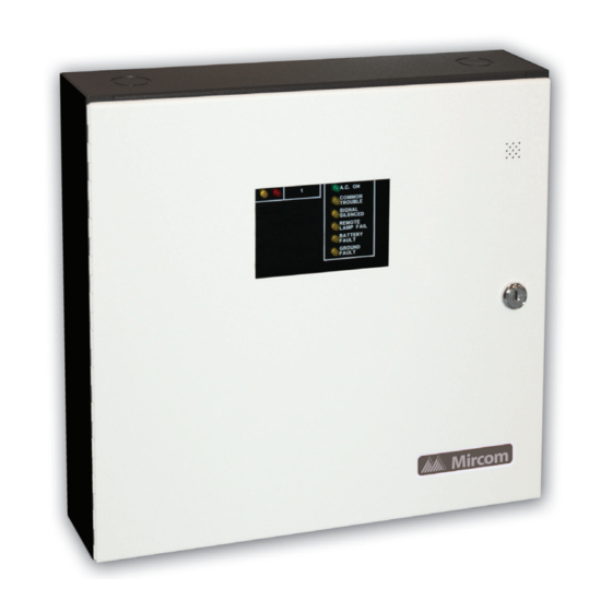
1. INTRODUCTION The FA-101U is a supervised 1 zone 24VDC Fire Alarm Control Panel. The panel provides the following features: - 1 class B detection zone - 1 class B signal zone, 1.25A - Alarm and trouble relay contacts - Remote trouble and A.C. ON indication... -
Page 4: Detection Zone
4. WIRING 4.1 DETECTION ZONES The system has 1 detection zone. Refer to Figure 3 for wiring instruction and to Figure 4 for wire size. 4.2 SIGNAL ZONE There is 1 signal zone available for bells and horns providing 1.25A of signal power. Refer to Figure 3 for wiring instruction and to Figure 5 for wire size. -
Page 5: Battery Fault Led
5.5 BATTERY FAULT LED Battery removal, low voltage and open battery leads will turn on the yellow battery fault LED and the common trouble LED. 5.6 GROUND FAULT LED Any ground fault of 10K ohms or less will turn on the yellow ground fault LED steadily, flashing the common trouble LED and sounding the common trouble buzzer intermittently. -
Page 6: System Checkout
7. SYSTEM CHECKOUT BEFORE TURNING POWER ON: 1. Check all external wiring for opens, shorts or grounds. 2. Check that transformer cables are securely connected. 3. Check the A.C. power wiring for proper connection. DO NOT connect batteries in order to prevent sparking. -
Page 7: Backbox & Flush Trim Mounting Details
FIGURE 1: BACKBOX & FLUSH TRIM MOUNTING DETAILS... - Page 8 FIGURE 2: CIRCUIT BOARD LAYOUT...
-
Page 9: Detection And Signal Wiring Instruction
FIGURE 3: DETECTION AND SIGNAL WIRING INSTRUCTION... -
Page 10: Wiring Table For Detection Zone
FIGURE 4: WIRING TABLE FOR DETECTION ZONE... -
Page 11: Wiring Table For Bells And Horns
FIGURE 5: WIRING TABLE FOR BELLS AND HORNS... -
Page 12: Remote Annunciation
FIGURE 6: ALARM AND TROUBLE RELAY CONTACTS AND REMOTE ANNUNCIATION WIRING INSTRUCTIONS -10-... - Page 13 2. Whether mixing different models of compatible smoke detectors, or using the same model on the same Circuit, total standby current of all detectors must not exceed 3 mA. SMOKE DETECTOR MAKE MODEL / BASE MAKE MODEL / BASE MAKE MODEL / BASE MIRCOM CERBERUS PYROTRONICS FENWAL MIR-525 D1-2 PSD-7131 / 70-201000-001...
- Page 14 A - A 0.12 mA 4451HT / B401B A - A 0.12 mA 4451HT / B406B A - A 0.12 mA MIRCOM 4451HT / B401 A - A 0.12 mA MIR-525U FDT-1 0.10 mA 5451 / B401B A - A 0.12 mA...
- Page 15 UNDERWRITER’S LABS INC. (ULI) UNITED STATES SIGNALING DEVICE CONTROL PANEL COMPATIBILITY System Sensor - SpecrAlert P2415 P2415W P241575 P241575W P2475 P2475W P24110 P24110W S2415 S2415W S241575 S241575W S2475 S2475W S24110 S24110W H12/24 H12/24W MDLW Wheelock AS-2415W-24-FR AS-241575W-FR AS-2430W-FR AS-2475W-FR AS-24110W-FR AS-2415C-FW AS-2430C-FW AS-2475C-FW...
-
Page 16: Appendix "B" Battery Calculations
POWER REQUIREMENTS (ALL CURRENTS ARE IN AMPERES) Model Number Description STANDBY TOTAL ALARM TOTAL STANDBY ALARM FA-101U Fire Alarm , 1 Det, 1 Sig 0.066 0.125 FA-102U Fire Alarm, 2 Det, 1 Sig 0.076 0.135 FA-1025U Fire Alarm, 5 Det, 2 Sig 0.114... - Page 18 Notes...
- Page 20 Advanced Life Safety Solutions Canada U.S.A. © Mircom 2006 Printed in Canada 25 Interchange Way 60 Industrial Parkway PMB 278 Subject to change without prior notice Vaughan, ON L4K 5W3 Cheektowaga, NY 14227 Tel: 1-888-660-4655 Fax: 1-888-660-4113 www.mircom.com Tel: 905-660-4655 Fax: 905-660-4113...
Need help?
Do you have a question about the FA-101U and is the answer not in the manual?
Questions and answers