Mircom FA-300 Series Installation And Operation Manual
Lcd fire alarm control panel
Hide thumbs
Also See for FA-300 Series:
- Installation and operation manual (106 pages) ,
- User manual (20 pages) ,
- Installation and operation manual (84 pages)
Table of Contents
Advertisement
Quick Links
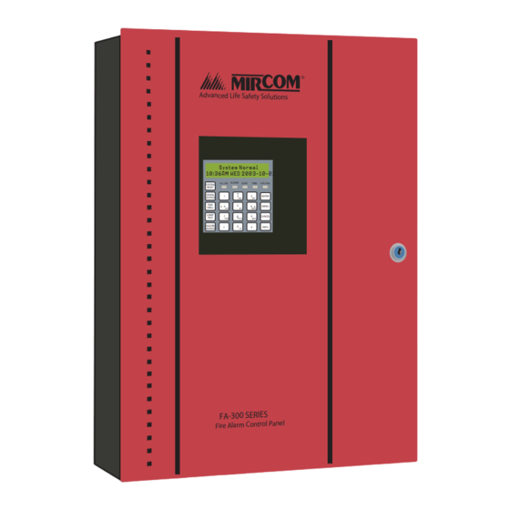
FA-300 Series
LCD Fire Alarm Control Panel
Advanc ed Life Safety Solutio ns
System Normal
10:36AM WED 2003-10-01
A.C. ON ALARM
SYSTEM
RESET
SIGNAL
1
SILENCE
FIRE
4
DRILL
GHI
LAMP
7
TEST
PQR
BUZZER
*
SILENCE
Installation and Operation Manual
SUPV
TRBL
CPU FAIL
2
3
ENTER
ABC
DEF
5
6
MENU
JKL
MNO
8
9
CANCEL
STU
WXY
0
#
INFO
YZ
LT-954 Rev. 1
February 2017
Advertisement
Table of Contents

Related Manuals for Mircom FA-300 Series


Summary of Contents for Mircom FA-300 Series
- Page 1 FA-300 Series LCD Fire Alarm Control Panel Advanc ed Life Safety Solutio ns System Normal 10:36AM WED 2003-10-01 A.C. ON ALARM SUPV TRBL CPU FAIL SYSTEM RESET SIGNAL ENTER SILENCE FIRE MENU DRILL LAMP CANCEL TEST BUZZER INFO SILENCE LT-954 Rev. 1...
-
Page 3: Table Of Contents
Table of Contents Introduction About this Manual ......................Technical Support ......................Main Display The Buzzer and LED Indicators Buzzer ..........................A.C. On LED ........................Alarm LED ........................Supervisory LED ......................Trouble LED ........................CPU Fail LED ......................... Main Display Buttons SYSTEM RESET ...................... - Page 4 List of Figures Figure 1 Main Display ........................Figure 2 LED Indicators ........................ Figure 3 Verified Alarm Example ....................Figure 4 Silenceable Signal Example ................... Figure 5 AC Power Fail ........................ Figure 6 Battery Trouble ....................... Figure 7 Ground Fault ........................Figure 8 RAU num mismatch .......................
-
Page 5: Introduction
Refer to the Glossary on page 18 for an explanation of terms used in this manual. Technical Support For all technical support inquiries, please contact Mircom’s Technical Support Department between 8 A.M. and 5 P.M. (EDT) Monday through Friday, excluding holidays. -
Page 6: Main Display
Main Display Figure 1 shows the LCD display, LED indicators, and control buttons locations. System Normal 18:01 2003-04-05 A.C. ON ALARM SUPV TRBL CPU FAIL SYSTEM RESET SIGNAL ENTER SILENCE FIRE MENU DRILL BUZZER CANCEL SILENCE LAMP INFO TEST Figure 1 Main Display The main display panel on the fire alarm control board consists of: •... -
Page 7: The Buzzer And Led Indicators
The Buzzer and LED Indicators A.C. ON ALARM SUPV TRBL CPU FAIL Figure 2 LED Indicators Buzzer The buzzer sounds if there is a fire alarm, a supervisory alarm, or a trouble in the fire alarm system. It turns off if the condition causing the buzzer to sound is cleared or if the BUZZER SILENCE button is pressed. -
Page 8: Main Display Buttons
Main Display Buttons SYSTEM RESET The SYSTEM RESET button resets the fire alarm control panel and all SYSTEM circuits. RESET SIGNAL SILENCE Pressing the SIGNAL SILENCE button when the panel is in alarm deactivates SIGNAL any silenceable signal devices in the fire alarm system. Non-silenceable SILENCE signal devices are unaffected. -
Page 9: Info
Main Display Buttons INFO Press the INFO button while the there is a message on the screen to view INFO additional information. ENTER, MENU, and CANCEL The ENTER, MENU, and CANCEL buttons are used by technicians to program the fire alarm control panel. -
Page 10: Disconnecting And Reconnecting A Circuit (Zone)
Disconnecting and Reconnecting a Circuit (Zone) You can disconnect and reconnect detection and signal circuits (zones) from the panel using the bypass options in the menu. To select the bypass options, you must be in the Command Menu. To enter the Command Menu, press MENU. -
Page 11: To Reconnect (Unbypass) A Circuit
Disconnecting and Reconnecting a Circuit (Zone) To Reconnect (Unbypass) a Circuit Step 1: Enter your passcode 1. Press MENU. Enter the 2. Enter your passcode. passcode 3. Press ENTER. ENTER Step 2: Select the Bypass menu 1. Use the up and down arrow buttons to scroll down to “Bypass Det Ckt”... -
Page 12: Understanding On-Screen Messages
Understanding On-screen Messages The screen of the fire alarm control panel displays messages regarding system events. System events display on the screen in a queue. Events in this queue are listed on the screen in order of priority: alarms are of highest priority, followed by supervisory, trouble, and monitor conditions. -
Page 13: Common Messages
Understanding On-screen Messages ZONE Process Physical Z O N E P ro ce ss P h ysic al Message Type Zone No. M essag e T yp e Z o n e N o . E A S T W I N G L O B B Y S I L E N C E - A B L E N A C - 1 “INFO”... -
Page 14: Ground Fault
Understanding On-screen Messages T ro u b le co d e T ro u b le In fo T ro u b le T yp e B a t t e r y T r o u b l e T r b : 0 x 0 3 I n f o : 0 x 0 0 0 8 "I N F O "... -
Page 15: 4Wire Pwr. Supply
Understanding On-screen Messages T ro u b le in fo T ro u b le T yp e T ro u b le c o d e R A U n u m m i s m a t c h T r b : 0 x 0 3 I n f o : 0 x 0 0 0 1 "IN F O "... -
Page 16: City Tie Polarity Reversal - Pr-300/Relay Module
Understanding On-screen Messages T ro u b le co d e T ro u b le In fo T ro u b le T yp e A u x . P o w e r S u p p l y T r b : 0 x 0 3 I n f o : 0 x 0 0 0 1 "I N F O "... -
Page 17: Figure 12 City Tie Trouble
Understanding On-screen Messages T ro u b le c o d e T ro u b le In fo T ro u b le T yp e C i t y T i e t r o u b l e T r b : 0 x 0 3 I n f o : 0 x 0 0 0 1 "IN F O "... -
Page 18: Glossary
Glossary Alarm Condition Occurs when devices such as detectors, pull stations, or sprinklers are activated. In a single stage system, this condition activates all signaling devices throughout the building. In a two stage system, this condition activates an alert signal and the General Alarm timer. Circuits Refers to an actual electrical interface and is classified as initiating (detection), indicating (signal), or relay. - Page 19 Glossary Non-Silenceable Circuit A signal circuit that cannot be silenced by pressing the SIGNAL SILENCE button. Relay Circuit A circuit in a fire alarm system that connects relay devices (for example, fan damper relays). Remote Annunciator A device that visually indicates, either by LCD or LEDs, the floor or zone where the alarm originated.
- Page 20 TECHNICAL SUPPORT U.S.A CANADA - Main Office © Mircom 2017 25 Interchange Way North America 4575 Witmer Industrial Estates Printed in Canada Subject to change without prior notice Tel: (888) Mircom5 Niagara Falls, NY 14305 Vaughan, ON L4K 5W3 Tel: (888) 660-4655...
Need help?
Do you have a question about the FA-300 Series and is the answer not in the manual?
Questions and answers