Sign In
Upload
Download
Table of Contents
Contents
Add to my manuals
Delete from my manuals
Share
URL of this page:
HTML Link:
Bookmark this page
Add
Manual will be automatically added to "My Manuals"
Print this page
×
Bookmark added
×
Added to my manuals
Manuals
Brands
Mircom Manuals
Control Panel
FA-103
Installation and operation manual
Mircom FA-103 Installation And Operation Manual
Fire alarm control panels
Hide thumbs
1
2
Table Of Contents
3
4
5
6
7
8
9
10
11
12
13
14
15
16
17
18
19
20
21
22
23
24
page
of
24
Go
/
24
Contents
Table of Contents
Troubleshooting
Bookmarks
Table of Contents
Table of Contents
Introduction
Mechanical Installation
Figure 1: Backbox and Flush Trim Mounting Details
Figure 2: Assembly of FA-106 and FA-103 Fire Alarm Panels
Clearances
Conduits for Wiring
Figure 3: Conduits for Wiring
Dip Switch Selection
Figure 4: Setting the DIP Switch Functions
Wiring
Detection (IDC) Zones
Signal (NAC) Zones
Alarm and Trouble Relays
Remote Annunciation
A.C. Power and Batteries
Figure 5: A.C. Power and Battery Connection
Figure 6: Circuit Board Layout
Figure 7: Detection and Signal Wiring
Wiring Tables and Information
Figure 8: Alarm and Trouble Relay Contacts, Remote Annunciation and Four-Wire Detector Wiring Instructions
Trouble Indicators and Controls
Common Trouble LED
Buzzer/Buzzer Silence Pushbutton
Detection Zone Trouble LED
Ground Fault LED
Battery Fault LED
Detection Zone Disable
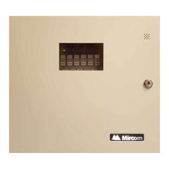
Figure 9: Front Panel Display
Sequence of Operation
Normal
Alarm
Signal Silence (SIG SIL)
Reset
Lamp Test
System Checkout
Power up and Troubleshooting
Appendix A: Electrical Specifications
Appendix B: Compatible Devices
Appendix C: Battery Calculations (Selection Guide)
Warranty and Warning Information
Advertisement
Quick Links
1
Figure 1: Backbox and Flush Trim Mounting Details
2
Dip Switch Selection
3
Figure 4: Setting the Dip Switch Functions
4
Detection (IDC) Zones
5
Signal (Nac) Zones
Download this manual
FA-103 and FA-106
Fire Alarm Control Panels
Installation and Operation Manual
Advanced Life Safety Solutions
LT-1200 Rev 2
March 2018
Table of
Contents
Previous
Page
Next
Page
1
2
3
4
5
Advertisement
Table of Contents
Need help?
Do you have a question about the FA-103 and is the answer not in the manual?
Ask a question
Questions and answers
Related Manuals for Mircom FA-103
Control Panel Mircom FA-1000 SERIES Installation And Operation Manual
Microprocessor-based fire alarm control panel (72 pages)
Control Panel Mircom FA-1000 Series Installation And Operation Manual
Microprocessor-based fire alarm control panel (88 pages)
Control Panel Mircom FA-101U Installation And Operation Manual
Fire alarm control panel (20 pages)
Control Panel Mircom FA-106 Installation And Operation Manual
Fire alarm control panels (24 pages)
Control Panel Mircom FA-106R Installation And Operation Manual
Fire alarm control panels (24 pages)
Control Panel Mircom FA-1025T Installation And Operation Manual
Fire alarm control panel (20 pages)
Control Panel MirCom FA-300 Series Installation And Operation Manual
Lcd fire alarm control panel (84 pages)
Control Panel Mircom FA-300 Series Installation And Operation Manual
Lcd fire alarm control panel (92 pages)
Control Panel Mircom FA-300 Series User Manual
Led fire alarm control panel (20 pages)
Control Panel Mircom FA-300 Series Installation And Operation Manual
Led fire alarm control panel (106 pages)
Control Panel Mircom FA-300 Series Installation And Operation Manual
Lcd fire alarm control panel (20 pages)
Control Panel Mircom FA-300 Series User Manual
Led fire alarm control panel (16 pages)
Control Panel Mircom FA-301-12LDW Installation And Operation Manual
Led fire alarm control panel (84 pages)
Control Panel Mircom FA-300-6L Series Installation And Operation Manual
Led fire alarm control panel (76 pages)
Control Panel Mircom FA-262 Installation And Operator's Manual
Fire alarm control panel (52 pages)
Control Panel Mircom FA-200 Series Installation And Operation Manual
Microprocessor-based fire alarm control panel (52 pages)
This manual is also suitable for:
Fa-106
Fa-103r
Fa-106r
Table of Contents
Print
Rename the bookmark
Delete bookmark?
Delete from my manuals?
Login
Sign In
OR
Sign in with Facebook
Sign in with Google
Upload manual
Upload from disk
Upload from URL


Need help?
Do you have a question about the FA-103 and is the answer not in the manual?
Questions and answers