Table of Contents
Advertisement
Quick Links
Advertisement
Table of Contents

Subscribe to Our Youtube Channel
Related Manuals for FAAC 3350.1


Summary of Contents for FAAC 3350.1
- Page 1 E024 U Control Board UL325 - UL991 FAAC International Inc. FAAC International Inc. West Coast Operations Headquarter & East Coast Operations 357 South Acacia Avenue 3160 Murrell Rd Fullerton, CA 92831 Rockledge, FL 32955 Tel. 800-221-8278 www.faacusa.com...
-
Page 2: Technical Specifications
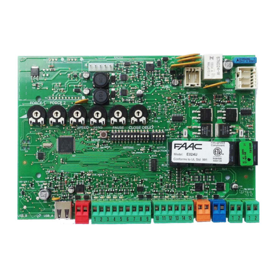
1. E024U CONTROL BOARD DESCRIPTION & CHARACTERISTICS SETTING DL14 DL15 DL16 DL17 DL18 DL19 DL20 DL21 DL22 Fig. A1 1.1 TECHNICAL SPECIFICATIONS 1.2 LAYOUT AND COMPONENTS Main power supply RADIO 115 V~ 60 Hz Connector for the radio receiver Secondary power BATTERY 24 Vdc - 16 A max. -
Page 3: Input / Output Description
2. INPUT / OUTPUT DESCRIPTION Encoder 24 VDC Maglock B STP CL OP OPEN Fig. A2 LABEL FUNCTION 2 EASY 2 EASY 2easy BUS input for encoders (S800H and S450H only), XIB and loop detector boards OPEN A N.O. Contact for total opening command OPEN B: N.O. -
Page 4: Safety Device Connections
3. SAFETY DEVICE CONNECTIONS Entrapment protection To comply with the UL325 standard for gate operators every Connection of One Pair of Monitored Closing Photocells entrapment zone, as defined in ASTMF2200, must be pro- tected by two independent entrapment protection devices. One of the devices is inherent in the E024U control boards design, the other can be external, like a photocell or an edge sensor. - Page 5 Only one monitored photocell can be connected to the Connection of One Pair of Closing Photocells Closing or Opening safety inputs. More than one photocell (monitored), One Pair of Opening Photocells or other device can be connected to the safety inputs, but (monitored) and One pair of Opening/Closing they will not be monitored.
-
Page 6: Operating Logic
4. PROGRAMMING 4.1 DIP SWITCH DS1 SETTINGS FOR OPERATING LOGIC OPERATING LOGIC DS 1: SW 1 - SW 2 - SW 3 PAUSE LOGIC SW 1 SW 2 SW 3 DESCRIPTION TIME E (default) One command opens, the next one closes. A command during opening stops the gate Semiautomatic 0 - 4... - Page 7 4.2 ADJUSTING TRIMMERS – FORCE ADJUSTMENT MOTOR 1 Turn clockwise to increase the opening and closing force TR 2 – FORCE ADJUSTEMENT MOTOR 2 Turn clockwise to increase the opening and closing force TR 3 – SPEED ADJUSTMENT FOR MOTOR1 AND MOTOR 2 Turn clockwise to increase the opening and closing speed TR 4 –...
- Page 8 4.3 DIP SWITCH DS1 SETTINGS FOR BOARD SETUP BOARD SETUP DS 1: SW 4 to SW 12 The opening of leaf 2 is delayed after the opening of leaf 1. This is to OPENING DELAY SW 4 avoid that the gate’s leafs interfere with each other during the initial part 0 sec (default) of the movement.
-
Page 9: Operator Selection
4.4 DIP SWITCH DS2 SETTINGS FOR OPERATOR TYPE AND LOCK MODE SETTING DL 1 DL 2 DL 3 DL 4 DL 5 IMPORTANT DS 2 DS 2 OPERATOR SELECTION LOCK OUTPUT MODE OPERATOR TYPE SW 1 SW 2 SW 3 OUTPUT MODE SW 4 S450H, S800H... - Page 10 LED STATUS In BOLD the normal state with gate closed and working DESCRIPTION ON STEADY BLINKING Board working on AC Board working on LED BATTERY power battery power or ext Battery charging supply LED +24 Main power OFF Main power present SLOW BLINK (1 sec.
-
Page 11: Led Error Display
The diagnostic LED shows only one error condition at a time, with the priority of the below table. In case there is more than one error once one is eliminated the LED will show the next LED ERROR DISPLAY NUMBER OF ERROR CONDITION SOLUTION FLASHES... -
Page 12: Obstacle Detection Function
At the point where you want the slowdown to start give an 7. ENCLOSURE OPEN A command with the push button or the remote that is already stored in memory. Leaf 2 starts to slow down and The E024U board is supplied on a panel that fits in a 16x14” stops when it reaches the mechanical stop or FCA2. -
Page 13: Ac Power Connection
8. POWER CONNECTION 8.1 POWER SUPPLY AC POWER GUIDELINES: The E024U board is powered by a high efficiency switching power supply that takes 115VAC input and provides 36VDC to THE E024U control board and power supply uses a single phase power the board. -
Page 14: Firmware Upgrade
DL 1 DL 2 DL 3 DL 4 DL 5 For the upgrade you need a USB Flash Drive, where you have to copy the file supplied by FAAC. Then follow these steps: SETTING Disconnect the batteries if they are present. -
Page 15: Function Logics
11. FUNCTION LOGICS LOGIC “E” PULSES SYSTEM STATUS OPEN A OPEN B STOP FSW OP FSW CL FSW CL/OP no effect no effect no effect CLOSED opens the leaves opens leaf 1 no effect (OPEN disabled) (OPEN disabled) (OPEN disabled) stops and opens at release immediately stops operation... - Page 16 LOGIC “EP” PULSES SYSTEM STATUS OPEN A OPEN B STOP FSW OP FSW CL FSW CL/OP no effect no effect no effect CLOSED opens the leaves opens leaf 1 no effect (OPEN disabled) (OPEN disabled) (OPEN disabled) stops and opens at release immediately OPENING stops operation (1) stops operation...
- Page 17 LOGIC “B” PULSES SYSTEM STATUS OPEN A OPEN B STOP FSW OP FSW CL FSW CL/OP no effect no effect no effect CLOSED opens the leaves no effect no effect (OPEN disabled) (OPEN disabled) (OPEN disabled) stops and, at release, closes OPENING no effect closes leaves...
-
Page 18: Limited Warranty
FAAC S.p.A. or FAAC International, Inc. The warranty herein FAAC International, Inc.’s obligations under above set forth shall not be deemed to cover...
Need help?
Do you have a question about the 3350.1 and is the answer not in the manual?
Questions and answers