Table of Contents
Advertisement
Quick Links
Advertisement
Table of Contents

Related Manuals for FAAC E024U


Summary of Contents for FAAC E024U
- Page 1 E024 U Control Board UL325 - UL991 FAAC International Inc. FAAC International Inc. West Coast Operations Headquarter & East Coast Operations 357 South Acacia Avenue 3160 Murrell Rd Unit 357 Rockledge, FL 32955 Fullerton, CA 92831 Tel. 800-221-8278 www.faacusa.com...
-
Page 2: Technical Specifications
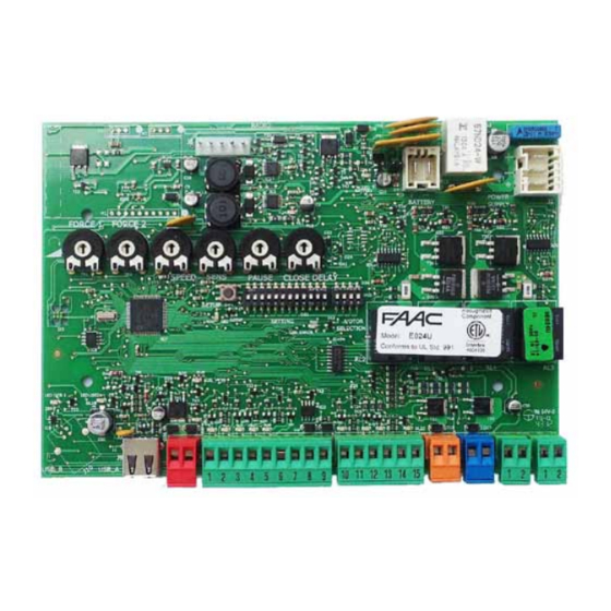
E024U CONTROL BOARD DESCRIPTION & CHARACTERISTICS SETTING DL14 DL15 DL16 DL17 DL18 DL19 DL20 DL21 DL22 Fig. A1 1.1 TECHNICAL SPECIFICATIONS 1.2 LAYOUT AND COMPONENTS Main power supply RADIO 115 V~ 60 Hz Connector for the radio receiver Secondary power BATTERY 24 Vdc - 16 A max. -
Page 3: Input / Output Description
2. INPUT / OUTPUT DESCRIPTION Encoder 24 VDC Maglock B STP CL OP OPEN Fig. A2 LABEL FUNCTION 2 EASY 2 EASY 2easy BUS input for the encoder OPEN A N.O. Contact for total opening command OPEN B / OPEN B: N.O. Contact for opening of leaf 1 only CLOSE (with only one leaf the opening stops at 50% of traveling) CLOSE (LOGIC B-C): N.O. - Page 4 (Connect them in series) Fig. A3 Fig. A4 The E024U board allows the connection of several safety devices (for example photocells). With photocells you can activate the FAILSAFE function, which, before each movement of the ope- rator, tests each fotocells. In case the test fails the movement is inhibited.
- Page 5 Connection of two pairs of closing photocells RX= Photocell Receiver TX= Ptotocell Transmitter STP CL OP CL= Closing OP= Opening Other optional safety devices to connect in series To use the FAIL-SAFE mode connect the nega- tive power supply of the transmitters to OUT (pin 9), and set dip-switch 11 and 12 to ON on DS1...
- Page 6 Connection of a pair of closing photocells and a pair of opening photocells STP CL OP RX= Photocell Receiver TX= Ptotocell Transmitter CL= Closing OP= Opening To use the FAIL-SAFE mode connect the negative power supply of the transmitters to OUT (pin 9), and set dip- switch 11 and 12 to ON on DS1 Fig.
-
Page 7: Operating Logic
PROGRAMMING 4.1 DIP SWITCH DS1 SETTINGS FOR OPERATING LOGIC OPERATING LOGIC DS 1: SW 1 - SW 2 - SW 3 PAUSE LOGIC DESCRIPTION TIME E (default) One command opens, the next one closes. A command du- OFF OFF OFF ring opening stops the gate Semiautomatic 0 - 4... - Page 8 4.2 ADJUSTING TRIMMERS – FORCE ADJUSTMENT MOTOR 1 Turn clockwise to increase the opening and closing force TR 2 – FORCE ADJUSTEMENT MOTOR 2 Turn clockwise to increase the opening and closing force TR 3 – SPEED ADJUSTMENT FOR MOTOR1 AND MOTOR 2 Turn clockwise to increase the opening and closing speed TR 4 –...
- Page 9 4.3 DIP SWITCH DS1 SETTINGS FOR BOARD SETUP BOARD SETUP DS 1: SW 4 to SW 12 The opening of leaf 2 is delayed after the opening of leaf 1. This is to avoid SW 4 OPENING DELAY that the gate’s leafs interfere with each other during the initial part of the 0 sec (default) movement.
-
Page 10: Led Diagnostics
4.4 DIP SWITCH DS2 SETTINGS FOR OPERATOR TYPE AND LOCK MODE SETTING DL 1 DL 2 DL 3 DL 4 DL 5 IMPORTANT DS 2 DS 2 OPERATOR SELECTION LOCK OUTPUT MODE OPERATOR TYPE SW 1 SW 2 SW 3 OUTPUT MODE SW 4 S450H, S800H... -
Page 11: Led Status
LED STATUS In BOLD the normal state with gate closed and working DESCRIPTION ON STEADY BLINKING Board working on AC Board working on LED BATTERY power battery power or ext Battery charging supply LED +24 Main power present Main power OFF SLOW BLINK (1 sec. -
Page 12: Led Error Display
The diagnostic LED shows only one error condition at a time, with the priority of the below table. In case there is more than one error once one is eliminated the LED will show the next LED ERROR DISPLAY NUMBER OF ERROR CONDITION SOLUTION FLASHES... -
Page 13: Obstacle Detection Function
OPEN A command with the push button or the remote that is already stored in memory. Leaf 2 starts to slow down and The E024U board is supplied on a panel that fits in a 16x14” stops when it reaches the mechanical stop or FCA2. -
Page 14: Power Connection
POWER CONNECTION 8.1 POWER SUPPLY AC POWER GUIDELINES: The E024U board is powered by a high efficiency switching power supply that takes 115V in input and provides 36VDC to power the THE E024U control board and power supply uses a single board. -
Page 15: Firmware Upgrade
9.1 DISABLE THE BATTERY CHARGER To disable the battery charger unplug jumper J24 The E024U board keeps the operating firmware in a field pro- grammable memory, it can be easily upgraded through the on J24 PRESENT = BATTERY CHARGING ACTIVE... -
Page 16: Function Logics
11. FUNCTION LOGICS LOGIC “E” PULSES SYSTEM STATUS OPEN A OPEN B STOP FSW OP FSW CL FSW CL/OP no effect no effect no effect CLOSED opens the leaves opens leaf 1 no effect (OPEN disabled) (OPEN disabled) (OPEN disabled) stops and opens at release immediately stops operation... - Page 17 LOGIC “EP” PULSES SYSTEM STATUS OPEN A OPEN B STOP FSW OP FSW CL FSW CL/OP no effect no effect no effect CLOSED opens the leaves opens leaf 1 no effect (OPEN disabled) (OPEN disabled) (OPEN disabled) stops and opens at release immediately OPENING stops operation (1) stops operation...
- Page 18 LOGIC “B” PULSES SYSTEM STATUS OPEN A OPEN B STOP FSW OP FSW CL FSW CL/OP no effect no effect no effect CLOSED opens the leaves no effect no effect (OPEN disabled) (OPEN disabled) (OPEN disabled) stops and, at release, closes OPENING no effect closes leaves...
-
Page 19: Limited Warranty
FAAC S.p.A. intended provided it has been properly installed or FAAC International, Inc. The warranty herein and operated.
Need help?
Do you have a question about the E024U and is the answer not in the manual?
Questions and answers