Table of Contents
Advertisement
Quick Links
INSTRUCTIONS–PARTS LIST
INSTRUCTIONS
WATERBASE COMPATIBLE
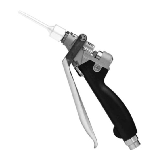
Ultra-lite
Model 235–627, Series B
4000 psi (280 bar) Maximum Working Pressure
Tapered Valve Needle
Model 235–628, Series B
6000 psi (415 bar) Maximum Working Pressure
Ball End Valve Needle, Abrasive Material Compatible
Model 237–607, Series A
4000 psi (280 bar) Maximum Working Pressure
Tapered Valve Needle, Abrasive Material Compatible
Model 237–649, Series A
4000 psi (280 bar) Maximum Working Pressure
Tapered Valve Needle, Abrasive Material Compatible,
Swivel Fitting Fluid Inlet
U.S. Patent No. Des. 342,654
GRACO INC. P.O. BOX 1441 MINNEAPOLIS, MN 55440–1441
This manual contains important
warnings and information.
READ AND RETAIN FOR REFERENCE
Pistol Grip Flo-Gun
COPYRIGHT 1992, GRACO INC.
308–253
Rev. F
Supersedes Rev. E
Advertisement
Table of Contents

Subscribe to Our Youtube Channel
Related Manuals for Graco Ultra-lite A Series


Summary of Contents for Graco Ultra-lite A Series
- Page 1 Tapered Valve Needle, Abrasive Material Compatible Model 237–649, Series A 4000 psi (280 bar) Maximum Working Pressure Tapered Valve Needle, Abrasive Material Compatible, Swivel Fitting Fluid Inlet U.S. Patent No. Des. 342,654 GRACO INC. P.O. BOX 1441 MINNEAPOLIS, MN 55440–1441 COPYRIGHT 1992, GRACO INC.
-
Page 2: Warning Symbol
Symbols Warning Symbol Caution Symbol WARNING CAUTION This symbol alerts you to the possibility of serious This symbol alerts you to the possibility of damage to injury or death if you do not follow the instructions. or destruction of equipment if you do not follow the instructions. -
Page 3: Fire And Explosion Hazard
Route the hoses away from the traffic areas, sharp edges, moving parts, and hot surfaces. Do not expose Graco hoses to temperatures above 180 F (82 C) or below –40 F (–40 C). Do not use the hoses to pull the equipment. -
Page 4: Ground The System
Installation Ground the System 3. Fluid hoses: use only grounded fluid hoses with a maximum of 500 feet (150 m) combined hose length to ensure grounding continuity. Check the WARNING electrical resistance of your fluid hoses at least once a week. If your hose does not have a tag on it which specifies the maximum electrical resis- FIRE AND EXPLOSION HAZARD tance, contact the hose supplier or manufacturer... - Page 5 Notes...
-
Page 6: Pressure Relief Procedure
Operation Pressure Relief Procedure Gun Trigger Safety WARNING WARNING INJECTION HAZARD INJECTION HAZARD To prevent accidental triggering of the The system pressure must be manually gun and reduce the risk of a serious in- relieved to prevent the system from jury, including fluid injection or splashing starting or spraying accidentally. - Page 7 Operation Dispensing Flushing Safety 1. Start the fluid supply pump. WARNING 2. The fluid flow rate is controlled at the pump. Adjust the pump pressure to obtain the desired flow rate. FIRE AND EXPLOSION HAZARD It is recommended that you use the lowest pres- To reduce the risk of a fire, explosion, or sure necessary to dispense the fluid.
- Page 8 Repair Description aged. Reassemble the gun or return it to your Model nearest Graco distributor. Do not use the gun 235–627 235–658* 6.5 needle, seat, urethane until the problem is corrected. seal When removing the gun from the hose, hold the 235–875...
-
Page 9: Adjusting The Valve
Service Adjusting the Valve 5. Turn the spring housing (28) and stem nut (1) to change the trigger travel and the size of the valve The trigger travel and corresponding valve opening are opening. factory set to 1 inch (25.4 mm). To adjust this setting, 6. - Page 10 Service Valve Stem and Seal Service 11. Lubricate the seal retainer (27). Torque the seal retainer into the gun body (17) to: If fluid leaks past the v-block seal (3), the v-block seal Models 235–627, 237–607, and 237–649: 50–60 or valve stem (24) may be worn or damaged. To in-lbs (5.6–6.8 N m).
- Page 11 Service NOTES: Torque to 6–10 in-lbs (0.68–1.13 N m) Models 235–627, 237–607, & 237–649: Torque to 70–80 in-lbs (7.9–9.0 N m) Model 235–628: Torque to 100–125 in-lbs (11.3–14.1 N m) Apply lithium base grease to threads Apply lithium base grease Models 235–627, 237–607, &...
- Page 12 Service Complete Disassembly and Assembly 12. Install the fluid tube (19) through the gun handle of the Gun (continued) (14) and screw it into the gun body (17). Torque the fluid tube (19) to: Assembly Models 235–627, 237–607, and 237–649: 50–60 1.
- Page 13 Service NOTES: Torque to 6–10 in-lbs (0.68–1.13 N m) Torque to 50–60 in-lbs (5.6–6.8 N m) Torque to 200–250 in-lbs (22.6–28.2 N m) Models 235–627, 237–607, & 237–649: Torque to 70–80 in-lbs (7.9–9.0 N m) Torque to 110–130 in-lbs (12.4–14.7 N m). Use the hex end of Model 235–628: Torque to 100–125 in-lbs (11.3–14.1 N m) the fluid tube (18) to reach the swivel fitting (19) torque Apply lithium base grease to threads...
- Page 14 Parts Models 235–627 and 237–607 Pistol Grip Flow Gun * 24 * 26...
- Page 15 Parts Model 235–627 Model 237–607 Pistol Grip Flow Gun Pistol Grip Flow Gun Ref. Ref. Part No. Description Qty. Part No. Description Qty. 100–975 NUT, hex; No. 5–40 100–975 NUT, hex; No. 5–40 102–233 BALL 102–233 BALL 102–921 SEAL, v-block; polyurethane 102–921 SEAL, v-block;...
- Page 16 Parts Models 237–649 Pistol Grip Flow Gun...
- Page 17 Parts Model 237–649 Ref. Part No. Description Qty. Pistol Grip Flow Gun 188–246 BRACKET, adjustment Ref. 188–247 SCREW, spring adjustment Part No. Description Qty. 188–253 NUT, nozzle 100–975 NUT, hex; No. 5–40 237–576 VALVE STEM; carbide & 17–4 102–233 BALL PH stainless steel 102–921 SEAL, v-block;...
- Page 18 Parts Model 235–628 Pistol Grip Flow Gun...
- Page 19 Parts Model 235–628 Pistol Grip Flow Gun Ref. Ref. Part No. Description Qty. Part No. Description Qty. 188–246 BRACKET, adjustment 100–975 NUT, hex; No. 5–40 188–247 SCREW, spring adjustment 102–233 BALL; stainless steel 188–253 NUT, nozzle 102–921 SEAL, v-block; polyurethane 236–234 STEM, valve 102–924...
-
Page 20: Technical Data
Technical Data Maximum Working Pressure Wetted Parts Model 235–627 Models 235–627, 237–607, Fluid Section ....Aluminum and 237–649 ... . 4000 psi (280 bar) Fluid Tube . - Page 21 Notes...
- Page 22 Notes...
- Page 23 Notes...
- Page 24 Graco distributor to the original purchaser for use. As purchaser’s sole remedy for breach of this warranty, Graco will, for a period of twelve months from the date of sale, repair or replace any part of the equipment proven defec- tive.
Need help?
Do you have a question about the Ultra-lite A Series and is the answer not in the manual?
Questions and answers