Table of Contents
Advertisement
Quick Links
Instructions - Parts List
WATERBASE COMPATIBLE
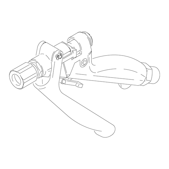
Ultra-litet Pistol Grip
Flo-Gun
Model 235627, Series B
4000 psi (280 bar) Maximum Working Pressure
Tapered Valve Needle
Model 235628, Series D
6000 psi (415 bar) Maximum Working Pressure
Ball End Valve Needle, Abrasive Material Compatible
Model 243775, Series B
6000 psi (415 bar) Maximum Working Pressure
Tapered Valve Needle
Model 237607, Series A
4000 psi (280 bar) Maximum Working Pressure
Tapered Valve Needle, Abrasive Material Compatible
Model 237649, Series A
4000 psi (280 bar) Maximum Working Pressure
Tapered Valve Needle, Abrasive Material Compatible,
Swivel Fitting Fluid Inlet
U.S. Patent No. Des. 342,654
. . . . . . . . . . . . . . . . . . . . . . . . . . . . . . . . . . . . . .
. . . . . . . . . . . . . . . . . . . . . . . . . . . . . . . . . . . . . . .
. . . . . . . . . . . . . . . . . . . . . . . . . . . . . . . . .
. . . . . . . . . . . . . . . . . . . . . . . . . . . . . . . . . . . . .
. . . . . . . . . . . . . . . . . . . . . . . . . . . . . . . . . . . . .
. . . . . . . . . . . . . . . . . . . . . . . . . . . . . . . . . . . . . . .
. . . . . . . . . . . . . . . . . . . . . . . . . . . . . . . . . . . . . . . .
. . . . . . . . . . . . . . . . . . . . . . . . . .
Important Safety Instructions
Read all warnings and instructions in this manual.
Save these instructions.
2
2
4
5
6
8
14
. . . . . . . . .
22
22
308253N
EN
01609A
Advertisement
Table of Contents

Related Manuals for Graco Ultra–lite 235627


Summary of Contents for Graco Ultra–lite 235627
-
Page 1: Table Of Contents
........Graco Warranty and Limitation of Liability . -
Page 2: Symbols
Symbols Warning Symbol Caution Symbol WARNING CAUTION This symbol alerts you to the possibility of serious This symbol alerts you to the possibility of damage to injury or death if you do not follow the instructions. or destruction of equipment if you do not follow the instructions. - Page 3 D This equipment is for professional use only. D Read all the instruction manuals, tags, and labels before operating the equipment. D Use the equipment only for its intended purpose. If you are uncertain about usage, call your Graco distributor.
-
Page 4: Technical Data
Technical Data Maximum Working Pressure Model 235628 Fluid Section ..17–4 PH Stainless Steel Models 235627, 237607, Fluid Tube ..300 Series Stainless Steel and 237649 ... . . 4000 psi (280 bar) Valve Needle . -
Page 5: Installation
Installation Ground the System 3. Fluid hoses: use only grounded fluid hoses with a maximum of 500 feet (150 m) combined hose length to ensure grounding continuity. Check the WARNING electrical resistance of your fluid hoses at least once a week. If your hose does not have a tag on FIRE AND EXPLOSION HAZARD it which specifies the maximum electrical resis- To reduce the risk of a fire, explosion,... -
Page 6: Operation
Operation Pressure Relief Procedure Gun Trigger Safety WARNING WARNING SKIN INJECTION HAZARD SKIN INJECTION HAZARD To prevent accidental triggering of the The system pressure must be manually gun and reduce the risk of a serious relieved to prevent the system from injury, including fluid injection or splash- starting or spraying accidentally. - Page 7 Operation Dispensing Flushing Safety 1. Start the fluid supply pump. WARNING 2. The fluid flow rate is controlled at the pump. Adjust the pump pressure to obtain the desired flow rate. FIRE AND EXPLOSION HAZARD It is recommended that you use the lowest pres- To reduce the risk of a fire, explosion, or sure necessary to dispense the fluid.
-
Page 8: Service
6.5_ needle, seat, urethane assembled properly or the trigger safety is seal damaged. Reassemble the gun or return it to your nearest Graco distributor. Do not use the 235875 PTFE seal, o-rings only gun until the problem is corrected. 235869... - Page 9 Service Adjusting the Valve 5. Turn the spring housing (28) and stem nut (1) to change the trigger travel and the size of the valve opening. The trigger travel and corresponding valve opening are factory set to 1 inch (25.4 mm). To adjust this setting, 6.
- Page 10 Service Valve Stem and Seal Service 11. Lubricate the seal retainer (27). Torque the seal retainer into the gun body (17) to: If fluid leaks past the v-block seal (3), the v-block seal Models 235627, 237607, and 237649: 50–60 or valve stem (24) may be worn or damaged. To in-lbs (5.6–6.8 NSm).
- Page 11 Service NOTES: Torque to 6–10 in-lbs (0.68–1.13 NSm) Models 235627, 237607, & 237649: Torque to 70–80 in-lbs (7.9–9.0 NSm) Models 235628 and 243775: Torque to 100–125 in-lbs (11.3–14.1 NSm) Apply lithium base grease to threads Apply lithium base grease Models 235627, 237607, & 237649: Torque to 50–60 in-lbs (5.6–6.8 NSm) Models 235628 and 243775: Torque to 100–125 in-lbs (11.3–14.1 NSm)
- Page 12 Service Complete Disassembly and Assembly 12. Install the fluid tube (19) through the gun handle (14) and screw it into the gun body (17). Torque of the Gun (continued) the fluid tube (19) to: Assembly Models 235627, 237607, and 237649: 50–60 in-lbs (5.6–6.8 NSm).
- Page 13 Service 24*}K 42{K 19{K NOTES: Torque to 6–10 in-lbs (0.68–1.13 NSm) Torque to 50–60 in-lbs (5.6–6.8 NSm) Models 235627, 237607, & 237649: Torque to 70–80 in-lbs Torque to 200–250 in-lbs (22.6–28.2 NSm) (7.9–9.0 NSm) Torque to 110–130 in-lbs (12.4–14.7 NSm). Use the hex end of Models 235628 and 243775: Torque to 100–125 in-lbs the fluid tube (18) to reach the swivel fitting (19) torque (11.3–14.1 NSm)
-
Page 14: Parts
Parts Models 235627 and 237607 Pistol Grip Flow Gun *{24 *{26 *{13 05446 14 308253... - Page 15 Parts Model 235627 Model 237607 Pistol Grip Flow Gun Pistol Grip Flow Gun Ref. Ref. Part No. Description Qty. Part No. Description Qty. 100975 NUT, hex; No. 5–40 100975 NUT, hex; No. 5–40 102233 BALL 102233 BALL 102921 SEAL, v-block; polyurethane 102921 SEAL, v-block;...
- Page 16 Parts Models 237649 Pistol Grip Flow Gun 04807 16 308253...
- Page 17 Parts Model 237649 Ref. Part No. Description Qty. Pistol Grip Flow Gun 188246 BRACKET, adjustment Ref. 188247 SCREW, spring adjustment Part No. Description Qty. 188253 NUT, nozzle 100975 NUT, hex; No. 5–40 237576 VALVE STEM; carbide & 17–4 102233 BALL PH stainless steel 102921 SEAL, v-block;...
- Page 18 Parts Model 235628 Pistol Grip Flow Gun 05447A 18 308253...
- Page 19 Parts Model 235628 Pistol Grip Flow Gun Ref. Ref. Part No. Description Qty. Part No. Description Qty. 188246 BRACKET, adjustment 188247 SCREW, spring adjustment 100975 NUT, hex; No. 5–40 188253 NUT, nozzle 102233 BALL; stainless steel 236234 STEM, valve 102921 SEAL, v-block;...
- Page 20 Parts Model 243775 Pistol Grip Flow Gun 05447A 20 308253...
- Page 21 Parts Model 243775 Pistol Grip Flow Gun Ref. Ref. Part No. Description Qty. Part No. Description Qty. 188247 SCREW, spring adjustment 100975 NUT, hex; No. 5–40 188253 NUT, nozzle 102233 BALL; stainless steel 237576 VALVE STEM; carbide & 17–4 102921 SEAL, v-block;...
-
Page 22: Graco Warranty And Limitation Of Liability
Graco distributor to the original purchaser for use. With the exception of any special, extended, or limited warranty published by Graco, Graco will, for a period of twelve months from the date of sale, repair or replace any part of the equipment determined by Graco to be defective.
Need help?
Do you have a question about the Ultra–lite 235627 and is the answer not in the manual?
Questions and answers