Graco SD Series Installation And Operation Instructions Manual
Cord and light reel
Hide thumbs
Also See for SD Series:
- Instructions manual (60 pages) ,
- Repair and parts manual (36 pages) ,
- Instructions manual (36 pages)
Table of Contents
Advertisement
Quick Links
Installation and Operation Instructions
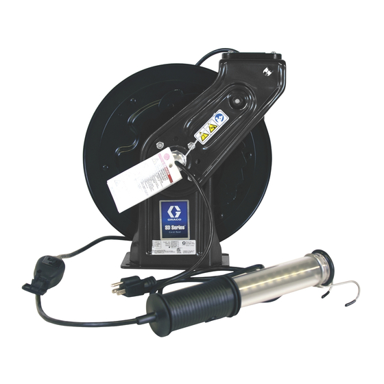
SD Series
Light Reel
For storing electric cord used to provide electricity and/or light. For indoor and dry
location use only.
Not approved for use in explosive atmospheres or hazardous locations.
Models: page 3 and 4
Important Safety Instructions
Read all warnings and instructions in
this manual. Save these instructions.
Size 5 Model
™
Cord and
Size 10 Model
3A2592M
EN
Advertisement
Table of Contents

Related Manuals for Graco SD Series


Summary of Contents for Graco SD Series
- Page 1 Installation and Operation Instructions ™ SD Series Cord and Light Reel 3A2592M For storing electric cord used to provide electricity and/or light. For indoor and dry location use only. Not approved for use in explosive atmospheres or hazardous locations. Models: page 3 and 4...
-
Page 2: Table Of Contents
Notes ....... . . 31 ™ Graco SD Series Cord and Light Reel Warranty 32 Related Manuals ™ 3A2826 - SD Series Cord and Light Reel Repair 3A2592M... -
Page 3: 120 Volt Models
120 Volt Models 120 Volt Models Power Cord Model Description Size Cord Length Insulation Connect Accessory Wire Gauge Current Black (AWG) (Amperes) Size 5 Size 10 50 feet NEMA SJTOW 24Y858 15 meters 5-15P 95 feet NEMA SJTOW 24Y879 29 meters 5-15P Cord, No Accessory... -
Page 4: 230 Volt Models
230 Volt Models 230 Volt Models Power Cord Cord Model Description Size Length Insulation Connect Accessory Current Black Wire Gauge (Amperes) Size 5 Size 10 24Y873 10 meters H05RR-F 1,5 mm Cord, No 24Y874 15 meters H05RR-F 1,5 mm Accessory 24Y888 25 meters H07RN-F 2,5 mm... -
Page 5: Warnings
Warnings Warnings The following warnings are for the setup, use, grounding, maintenance, and repair of this equipment. The exclama- tion point symbol alerts you to a general warning and the hazard symbols refer to procedure-specific risks. When these symbols appear in the body of this manual or on warning labels, refer back to these Warnings. Product-spe- cific hazard symbols and warnings not covered in this section may appear throughout the body of this manual where applicable. - Page 6 Warnings FIRE AND EXPLOSION HAZARD When flammable fluids are present in the work area, such as gasoline and windshield wiper fluid, be aware that flammable fumes can ignite or explode. To help prevent fire and explosion: • When installing a cord reel above a hazardous location the reel must be mounted at such a height that the lamp guard cannot reach within 18 inches of the floor.
-
Page 7: Component Identification
Component Identification Component Identification Key: Spool Power Cord Accessory Cord cord stop Base Plate Support Arm cutaway view - part is located behind support arm) Pawl ( 3A2592M... -
Page 8: Installation
Installation Installation General Installation Information All Models Select the reel bank mounting location. • For high ceilings, suspend a suitable support structure for the reels, so the accessory cords will be long enough to reach your service area. To reduce the risk of injury from electric shock and fire and explosion: 1. -
Page 9: Mounting
Installation Mounting Incorrect The electric cord reel is heavy and may be difficult to mount without assistance. (See Technical Data, page 26 for weights of cord reel assemblies.) To reduce the risk for injury: • Be sure the mounting surface and bolts are strong enough to support the cord reel’s weight and stress caused by hard pulls on the accessory cord. - Page 10 Installation 6. If needed, adjust spring tension. See the Increasing Spring Tension or Decreasing Spring Tension sec- tion of this manual, page 14. 7. Position cord stop at a height that is easily accessi- ble to the user. Tighten nuts to securely hold stop in place.
- Page 11 For Size 5 Models mounted in an Size 10 Model Mounting Channel: Size 5 models require a specific hold down plate designed for Size 5 Cord Reels. Contact Graco Customer Service for assistance when ordering these parts. NOTE: See page 16 for Open Channel dimensions.
- Page 12 Installation Ceiling Mounting to I-Beam without Drilling NOTE: For enclosed reels, use the Enclosure Kit Base Holes Plate (Part No. 302, page 15). (Order Mounting Bracket Kit: 204741 for open or enclosed reels.) NOTE: For mounting 1-3 reels, two kits are required. For mounting 4-6 reels, three kits are required.
- Page 13 Installation Swivel Bracket Mounting Kit • 24N444 for Size 10 Models • 24N814 for Size 5 Models Installation instructions are included with the kit. 3A2592M...
-
Page 14: Adjusting Spring Tension
Installation Adjusting Spring Tension Decreasing Spring Tension 1. Disconnect cord reel from power source by unplug- ging power cord from outlet. 2. Pull out accessory cord, 1 to 2 turns and engage • Never allow reel to spin freely. Doing so could pawl. -
Page 15: Enclosed Channel Kits
• Size 10 Dark Blue - 24A943 Enclosed Channel Mounting Kits are available from Graco. Installation instructions are included with the kit. Contact Graco Customer Service for additional information about ordering these kits. Size 5/Size 10 Enclosed Mounting Channel Kit: •... -
Page 16: Gfci Models Installation In Enclosures
Installation GFCI Models - 24Y864, 24Y883: Reassembly Installation In Enclosures 1. Route cord through enclosure panel and through opening in roller guide. 2. Connect green wire from cord to green terminal from GFCI module. Connect black wire from cord to brass terminal. Connect white wire from cord to silver terminal. -
Page 17: Light Models Installation In Enclosures
Installation Light Models Installation In 1. Insert light assembly (A) through roller bracket opening (B) located in the top of side panel (307). Enclosures 2. Remove the roller and pin assembly (13b and 13c) from the roller bracket (13a). Slide the bracket over the top of the light and hanger assembly. -
Page 18: Mounting Channel Dimensions
Mounting Channel Dimensions Mounting Channel Dimensions (Side dimension for all kits) 1 Reel Base - Used with Size 5 Kit 24N674 and Size 10 Kits 24A934 / 203521 9.0 inch/228.6 mm 4 x 3/8-16 UNC-2B Weld Nut 7.50 inch/ 190.5 mm 0.50 inch/12.7 mm 6.75 inch 171.4 mm... -
Page 19: Reel Base Weldment
Mounting Channel Dimensions 3 Reel Base Weldment 4-Reel Base Weldment Used with Kits 24A936, 203523 Used with Kits 24A937, 203524 7.75 in. / 7.75 in. / 196.8 mm 196.8 mm 0.75 inch/ 0.75 inch/ 19.05 mm 19.05 mm 6.75 in/ 0.50 inch/ 171.4 mm 12.7 mm... -
Page 20: Reel Base Weldment
Mounting Channel Dimensions 5 Reel Base Weldment 6-Reel Base Weldment Used with Kits 24A939, 203526 Used with Kits 24A938, 203525 7.75 in. / 196.8 mm 7.75 in. / 196.8 mm 0.75 inch/ 19.05 mm 0.75 inch/ 19.05 mm 6.75 in/ 171.4 mm 0.50 inch/ 12.7 mm... -
Page 21: Side Dimension (All Models)
Mounting Channel Dimensions Side Dimension (All Models) 2.5 inch/63.5 mm 3A2592M... -
Page 22: Troubleshooting
Troubleshooting Troubleshooting Repair instructions for some of the Solutions in this Troubleshooting Table are included in a separate repair instruc- tion manual for this product. Problem Cause Solution Cord will not retract fully Outlet attachment is too heavy Increase spring tension. See Increasing Spring Tension, page Spring lost tension Spring is broken... - Page 23 Troubleshooting Problem Cause Solution Check electrical rating on reel label. Application does not conform to Do not attempt to use a reel that is the electrical rating of the reel Breaker or fuse trip out (GFCI not rated for the application. accessory or European models Wires are broken or shorted Replace all damaged wires.
-
Page 24: Sd Series ™ Cord And Light Reel Kits
24P164 KIT, Size 5 enclosed reel mounting bracket power cord replacement kit ™ * Order this kit if you have existing Size 10 SD Series Accessory Cord Kits Enclosure and you want to mount a Size 5. 35 ft, 12 AWG 3 conductor, SJOOW acces-... - Page 25 ™ SD Series Cord and Light Reel Kits Kit No. Description Kit No. Description 20A Single Industrial Receptacle Tool Tap for LED light models 24N871 NEMA 5-20R replacement kit 16N226 Power Pod tool tap Ball Stop Kit Repair kits 2.5mm...
- Page 26 Technical Data Technical Data ™ Size 5 and Size 10 SD Series Cord and Light Reel 120V Models 230V Models Voltage 120VAC 230VAC Maximum Current See Models, page 3 See Models, page 4 Wire Gauge See Models, page 3 See Models, page 4...
-
Page 27: Technical Data
Technical Data Dimensions - Size 5 and Size 10 Models Size E† 3.5 inches 6.38 inches 4.7 inches 7.48 inches 14.8 inches 6.6 inches 13.84 inches Size 5 (89 mm) (162 mm) (120 mm) (190 mm) (376 mm) (168 mm) (352mm) 3.5 inches 7.5 inches... - Page 28 Mounting Templates Mounting Templates NOTE: True-to-size Size 5 and Size 10 Mounting Templates are provided as the last two pages of this manual. Before using these templates read NOTE regarding verification of template size. ***NOTE*** 4.72 in. (120.0 mm) Due to printer variations the size of the template MUST be verified for 3.5 in.
-
Page 29: Mounting Templates
Mounting Templates 3A2592M... - Page 30 ***NOTE*** 4.75 in. (119.89 mm) Due to printer variations the size of 3.5 in (88.9 mm) the template MUST be verified for accuracy prior to using. To verify the template is the correct size, using the true to size template provided on the last pages of this manual, measure the length of the two...
-
Page 31: Notes
Notes 3A2592M... -
Page 32: Graco Sd Series Cord And Light Reel Warranty
With the exception of any special, extended, or limited warranty published by Graco, Graco will, for a period from the date of sale as defined in the table below, repair or replace equipment covered by this warranty and determined by Graco to be defective. - Page 33 Graco 2-Year Extended Warranty 3.5 in. (88.9 mm) 3A2592M...
- Page 34 Graco 2-Year Extended Warranty THIS PAGE IS INTENTIONALLY LEFT BLANK 3A2592M...
- Page 35 Graco 2-Year Extended Warranty 3.5 in. (88.9 mm) 3A2592M...
- Page 36 Original instructions. This manual contains English. MM 3A2592 Graco Headquarters: Minneapolis International Offices: Belgium, China, Japan, Korea GRACO INC. AND SUBSIDIARIES • P.O. BOX 1441 • MINNEAPOLIS MN 55440-1441 • USA Copyright 2012, Graco Inc. All Graco manufacturing locations are registered to ISO 9001. www.graco.com...
Need help?
Do you have a question about the SD Series and is the answer not in the manual?
Questions and answers