Table of Contents
Advertisement
Quick Links
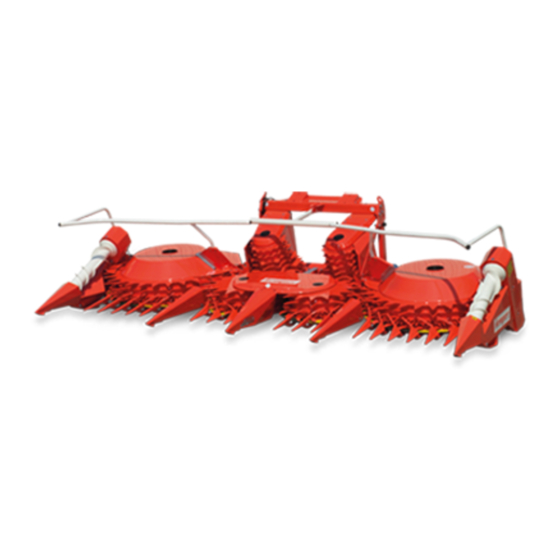
445
Rotary harvesting unit
OPERATOR'S MANUAL
445 Rotary harvesting unit
OMKM123308 ISSUE A9
(ENGLISH)
CALIFORNIA
Proposition 65 Warning
Diesel engine exhaust and some of its constituents
are known to the State of California to cause cancer,
birth defects, and other reproductive harm.
If this product contains a gasoline engine:
WARNING
The engine exhaust from this product contains
chemicals known to the State of California to cause
cancer, birth defects or other reproductive harm.
The State of California requires the above two warnings.
Additional Proposition 65 Warnings can be found in this manual.
Maschinenfabrik Kemper GmbH & Co. KG
European Version
PRINTED IN GERMANY
Advertisement
Table of Contents

Subscribe to Our Youtube Channel
Related Manuals for Kemper 445


Summary of Contents for Kemper 445
- Page 1 State of California to cause cancer, birth defects or other reproductive harm. The State of California requires the above two warnings. Additional Proposition 65 Warnings can be found in this manual. Maschinenfabrik Kemper GmbH & Co. KG European Version PRINTED IN GERMANY...
- Page 2 To order, see your KEMPER dealer. risks must be borne solely by the user. THIS MANUAL SHOULD BE CONSIDERED a permanent...
-
Page 3: Table Of Contents
Transport With Harvesting Unit Installed ....05-7 Ballasting for Safe Ground Contact ....05-7 Operating the Rotary Harvesting Unit Remove Paint Before Welding or Heating..05-8 Principle of Operation of the 445 Correct Disposal of Waste........05-8 Rotary Harvesting Unit ........35-1 Avoid High-Pressure Jet on Safety Decals..05-8 Operating the Rotary Harvesting Unit - Decommissioning —... - Page 4 Page Length-of-Cut Adjustment with NEW HOLLAND Forage Harvester ......35-5 Specifications Lengths of Cut and Drum Speeds with 445 Rotary Harvesting Unit ........65-1 NEW HOLLAND Forage Harvester....35-6 Sound Level............65-1 Harvesting Down Crop ........35-7 EU Declaration of Conformity ......65-2 Harvesting Short Stalks with Corn......35-7 Whole Crop Silage (WCS)........35-8...
-
Page 5: Pre-Delivery Inspection
Pre-delivery Inspection Predelivery Checklist After the 445 rotary harvesting unit has been completely □ Shipping brackets removed. assembled, inspect it to be sure it is in good running order before delivering it to the customer. Check off each item □ Rotary harvesting unit can be folded correctly. -
Page 6: After-Sale Checklist
Pre-delivery Inspection After-Sale Checklist The following items should be checked sometime during □ Check for worn rotary knives. the first season of operation with the rotary harvesting unit. □ Check with the customer as to the performance of the □ Go over the entire machine for loose or missing nuts rotary harvesting unit thus far. -
Page 7: Identification View
Identification View Identification View KM00321,0000882 -19-07JAN19-1/1 00-1 021519 PN=7... -
Page 8: Safety Measures
Replacement safety signs are available from your KEMPER dealer. Before you start working with the machine, learn how to operate the machine and how to use controls properly. Do not let anyone operate without instruction. -
Page 9: Observe Road Traffic Regulations
Safety Measures Observe Road Traffic Regulations Always observe local road traffic regulations when using public roads. FX,ROAD -19-01MAY91-1/1 Operator Ability and/or controls, and operating the machine properly and safely. • Machine owners must make sure that operators • Never allow a child or an untrained person to operate are responsible, trained, have read the operating the machine. -
Page 10: Prepare For Emergencies
Safety Measures Prepare for Emergencies Be prepared if a fire starts. Keep a first aid kit and fire extinguisher handy. Keep emergency numbers for doctors, ambulance service, hospital, and fire department near your telephone. DX,FIRE2 -19-03MAR93-1/1 Wear Protective Clothing Wear close fitting clothing and safety equipment appropriate to the job. -
Page 11: Guards And Shields
Safety Measures Guards and Shields Keep guards and shields in place at all times. Ensure that they are serviceable and installed correctly. Always disengage main clutch, shut off engine and remove key before removing any guards or shields. Keep hands, feet and clothing away from moving parts. FX,DEVICE -19-04DEC90-1/1 Stay Clear of Harvesting Units Due to their function, the cutting, gatherer and feed drums... -
Page 12: Store Attachments Safely
Safety Measures Store Attachments Safely Stored attachments such as dual wheels, cage wheels, and loaders can fall and cause serious injury or death. Securely store attachments and implements to prevent falling. Keep playing children and bystanders away from storage area. DX,STORE -19-03MAR93-1/1 Practice Safe Maintenance Understand service procedure before doing work. -
Page 13: Stay Clear Of Rotating Drivelines
Safety Measures Stay Clear of Rotating Drivelines Entanglement in rotating driveline can cause serious injury or death. Keep all shields in place at all times. Make sure rotating shields turn freely. Wear close-fitting clothing. Stop the engine and be sure that all rotating parts and drivelines are stopped before making adjustments, connections, or performing any type of service on engine or machine driven equipment. -
Page 14: Avoid High-Pressure Fluids
Safety Measures Avoid High-Pressure Fluids Escaping oil under pressure can have sufficient pressure to penetrate the skin, causing serious personal injury. Avoid the hazard by relieving pressure before disconnecting hydraulic or other lines. Check and tighten all connections before applying pressure. Hydraulic oil escaping from pin-holes is difficult to detect, so use a piece of cardboard to search for leaks. -
Page 15: Remove Paint Before Welding Or Heating
Correct Disposal of Waste Incorrect disposal of waste may damage the environment and ecological systems. Potentially harmful waste used with KEMPER equipment includes such items as oil, fuel, coolant, brake fluid, filters, and batteries. Use leak-proof containers when draining fluids. Do not use food or beverage containers that may mislead someone into drinking from them. -
Page 16: Decommissioning - Proper Recycling And Disposal Of Fluids And Components
• Contact your local environmental or recycling center, or or ordinances governing the handling or disposal of your KEMPER dealer for information on the proper way waste fluids (example: oil, fuel, coolant, brake fluid); to recycle or dispose of waste. -
Page 17: Safety Decals
Safety Decals Pictorial Safety Signs At several important places of this machine safety signs are affixed intended to signify potential danger. The hazard is identified by a pictorial in a warning triangle. An adjacent pictorial provides information how to avoid personal injury. -
Page 18: Repair And Maintenance
Safety Decals Repair and Maintenance Before carrying out repair or maintenance work, shut off engine and remove key. KM00321,0000885 -19-16JAN19-1/1 Feed Components of the Rotary Harvesting Unit Stay away from the rotary harvesting unit to avoid injuries. Arms, legs, or loose clothing can get caught in the rotary harvesting unit during operation. -
Page 19: Rotating Blades
Safety Decals Rotating Blades Do not touch any moving machine parts. Wait until it has stopped entirely. The rotating blades are not immediately stopped when the machine is shut down. Rotating blades can catch arms, legs or loose clothing as long as they are in motion and can cause serious injury. -
Page 20: Input Transmission
Safety Decals Input Transmission Excessive heat may develop at the input transmission. Stay clear of hot surfaces. Hot surfaces may cause serious burns. KM00321,000088B -19-16JAN19-1/1 10-4 021519 PN=20... -
Page 21: Attaching To A Claas Forage Harvester
Attaching to a CLAAS Forage Harvester Compatibility Chart (Forage Harvester Types out the steps included in Section Prepare 492, 493, 494, 496, 497, and 498) the Rotary Harvesting Unit. The rotary harvesting unit is prepared for installation on CAUTION: Before attaching the rotary the following CLAAS forage harvester types: harvesting unit to a forage harvester, carry Compatibility chart rotary harvesting unit/CLAAS forage harvester... - Page 22 Attaching to a CLAAS Forage Harvester 2. Drive the forage harvester close to the rotary harvesting unit's frame until latching hooks (A) protrude into brackets (B) of the attaching frame. 3. Lift the pressing rollers housing of the forage harvester until the rotary harvesting unit lies with the latching hooks (A) in the brackets (B).
- Page 23 Attaching to a CLAAS Forage Harvester 5. Fit the clamping piece (A) on both sides. A—Clamping piece KM00321,0000896 -19-23JAN19-4/6 6. Raise the jackstand (A) on the left and right sides and secure it in the uppermost position with a spring-loaded pin. A—Jackstand B—Spring-loaded pin KM00321,0000896 -19-23JAN19-5/6...
-
Page 24: Connecting The Drive (Forage Harvester Types 493, 494, 497 And 498)
Attaching to a CLAAS Forage Harvester Connecting the Drive (Forage Harvester Types 493, 494, 497 and 498) 1. Completely remove claw clutch (A) from rotary harvesting unit drive. To do this, disassemble items 1 to 11. A—Claw clutch KM00321,0000897 -19-28JAN19-1/9 2. - Page 25 Attaching to a CLAAS Forage Harvester 3. Push the universal-jointed shaft (A) onto the transmission of the rotary harvesting unit until the sliding pin (B) engages. A—Universal-jointed shaft B—Sliding pin KM00321,0000897 -19-28JAN19-3/9 4. Press the sliding pin (C) and guide the splined shaft (B) so far into the universal-jointed shaft (A) until the sliding pin (C) engages.
- Page 26 Attaching to a CLAAS Forage Harvester 5. Secure the splined shaft with screw (C), tooth lock washers (B) and washer (A). A—Screw C—Holder B—Tooth lock washer (3 pieces) KM00321,0000897 -19-28JAN19-5/9 Installing the Universal-jointed Shaft Shield (Claas 493, 494 and 497) 1.
- Page 27 Attaching to a CLAAS Forage Harvester Installing the Universal-jointed Shaft Shield (Claas 498) 1. Fix adapter (A) with flange screws (B). NOTE: Insert washers (C) as needed. A—Adapter C—Washers B—Flange screw KM00321,0000897 -19-28JAN19-7/9 2. Install holder (A) with cap screws (B). A—Holder B—Cap screws Continued on next page...
-
Page 28: Connecting The Drive (Forage Harvester Type 496)
Attaching to a CLAAS Forage Harvester 3. Install the universal-jointed shaft shield (A) and secure it with quick-lock pin (B) and lock nut (C). A—Universal-jointed shaft C—retaining nut shield D—Washer B—Quick-lock pin KM00321,0000897 -19-28JAN19-9/9 Connecting the Drive (Forage Harvester Type 496) 1. - Page 29 Attaching to a CLAAS Forage Harvester 3. On the rear of the header drive, carefully force out the cap (A) using a 35 mm dia. shaft. A—Cap Continued on next page KM00321,0000898 -19-28JAN19-2/6 20-9 021519 PN=29...
- Page 30 Attaching to a CLAAS Forage Harvester KM370762 —UN—23JAN19 4. Insert the splined shaft (A) on the front of the header drive. 5. Secure it with bushing (B) on the back of the header drive. 6. Insert screw (C) with washer (D) and tighten it. A—Splined shaft C—Screw B—Bushing...
- Page 31 Attaching to a CLAAS Forage Harvester Installing the Universal-jointed Shaft Shield (Claas 496) 1. Pre-assemble the bracket and install it on the header drive of the forage harvester. A—Shaft D—Washer B—Compression spring E—Snap ring C—Washer KM00321,0000898 -19-28JAN19-5/6 2. Install the universal-jointed shaft shield (A) and secure it with washer (B), lock nut (C) and quick-lock pin (D).
-
Page 32: Replace Claas Tray With Kemper Tray
This problem will be resolved by using the straight KEMPER tray (A). Installation: Remove CLAAS tray, slide in straight KEMPER tray (A) and attach it to support shaft (B). NOTE: When harvesting grass, remove the KEMPER tray. -
Page 33: Compatibility Chart
Section Preparing the Rotary Harvesting Unit. Compatibility chart for rotary harvesting unit/NEW HOLLAND forage harvester ............445 Rotary Harvesting Unit FX 30 FX 40 FX 50 FX 60 KM00321,0000891 -19-17JAN19-1/1... -
Page 34: Connecting The Driveshaft
Attaching to a NEW HOLLAND Forage Harvester Attaching to a NEW HOLLAND Forage Harvester 1. Drive the forage harvest slowly forward until the mounting rail (A) lies in the attaching frame of the rotary harvesting unit. Then raise the front shield and engage the rotary harvesting unit. -
Page 35: Install Guards For U.j. Shaft On Forage Harvester
Attaching to a NEW HOLLAND Forage Harvester Install Guards for U.J. Shaft on Forage Harvester Cover both splined shafts (A) and (B) with protective guard (D). Depending on which splined shaft is used (A or B) the cover plate (1) must be installed on the top or on the bottom of strap (2). -
Page 36: Transport
Transport Driving on Public Roads regulations when driving the forage harvester on public roads. CAUTION: When driving on public roads or Fold the outer sections for transport according to the local highways at night or during the day, observe local regulations. -
Page 37: Hanging Points
Transport Hanging Points CAUTION: Always use the hanging points (see arrows). This will prevent the machine from toppling over. Make sure to use chains or slings that meet the weight requirements of the rotary harvesting unit (see "Technical Specifications" section). Particular care must be taken when loading in this way. -
Page 38: Operating The Rotary Harvesting Unit
Operating the Rotary Harvesting Unit Principle of Operation of the 445 Rotary Harvesting Unit A—Feeder house drum D—Rotating blade G—Feed teeth J— Row of teeth B—Intake bars E—Direction of crop H—Guides and scrapers K—Rotating blade C—Feeder house drum F— Feed drum I—... -
Page 39: Operating The Rotary Harvesting Unit - General Use
Operating the Rotary Harvesting Unit Operating the Rotary Harvesting Unit - Operating the Rotary Harvesting Unit General Use Once the cutterhead is turning at the correct speed, and Starting the Forage Harvester the rotary cutters are at the appropriate speed, drive into the standing crop. -
Page 40: Removing The Tensioning Strap
Operating the Rotary Harvesting Unit Removing the Tensioning Strap Remove the tensioning strap (A). NOTE: Do NOT throw away the tensioning strap (A). Reinstall the tensioning strap (A) when driving on public roads so that the outer mowing units do not lower. A—Tensioning strap KM00321,000089A -19-22JAN19-1/1 Adjusting the Feed Bar... -
Page 41: Operating The Rotary Harvesting Unit
See forage harvester operator's manual for adjustments of the forage harvester. On the KEMPER rotary harvesting unit, 1st gear and 2nd gear are shifted with the shift lever (A) at the drive case. • Shift lever (A) inserted (as shown): First gear •... -
Page 42: Overview Of The Length Of Cuts For Claas Forage Harvesters Of The Types 493-498
HOLLAND Forage Harvester IMPORTANT: On forage harvesters equipped with infinitely variable length-of-cut adjustment HYDROLOC, the drum speed of the KEMPER rotary harvesting unit must not exceed 33 rpm. This is equivalent to an input speed at the drive gear of the rotary harvesting unit of max. -
Page 43: Lengths Of Cut And Drum Speeds With New Holland Forage Harvester
Operating the Rotary Harvesting Unit On the KEMPER rotary harvesting unit, 1st gear (A) and 2nd gear (B) are shifted directly at the drive gear case. IMPORTANT: The drum speed must not exceed 33 rpm! A—1st gear B—2nd gear KM00321,00008A1 -19-22JAN19-3/3... -
Page 44: Harvesting Down Crop
Operating the Rotary Harvesting Unit Harvesting Down Crop By driving round the field once, the operator will get an idea of which direction works best for harvesting the crop. Observe how the rotary harvesting unit feeds in the crop. Usually, it is recommended to start harvesting the crop at a right angle to the direction of the plants. -
Page 45: Whole Crop Silage (Wcs)
Operating the Rotary Harvesting Unit Whole Crop Silage (WCS) For harvesting the whole crop silage, install special mounting kit as follows, which is available from a spare parts dealer: 1. Remove the divider points between the two feeder house drums (left and right) including the bearing support and replace them with the short GPS divider points (A). -
Page 46: Additional Equipment
Additional Equipment Special Kit for Row Guidance (Steering A special kit is available as an attachment and is Assistance) composed of: When driving forage harvester 90 % of the driver's • (1) sensor system with connecting cables attention is focused on steering. Use of the entire machine •... -
Page 47: Troubleshooting
Troubleshooting 445 Rotary Harvesting Unit remove ignition key and wait until all moving parts have come to a stop. CAUTION: Before carrying out adjustment or maintenance work, ALWAYS shut off engine, Symptom Problem Solution Power requirement becomes Rotating blades are dull Replace segments. - Page 48 Bad cut with wide row spacing The middle row of plants is located Approach only four rows if they are far in the middle of the rotary harvesting apart. Contact a KEMPER deale. unit, if 5 rows are approached KM00321,00008A3 -19-22JAN19-2/2 45-2...
-
Page 49: Lubrication And Periodic Service
Lubrication and Periodic Service Service Intervals IMPORTANT: Replace any damaged parts. Any screws that have worked loose must be CAUTION: Before making any adjustments or retightened to the proper torque. doing any service work, always: - Switch the machine off Clean grease fittings before lubrication. -
Page 50: Transmission Oil
A 50:50 mixture of ethylene coolant in water provides coolant. freeze protection to -37°C (-34°F). If protection at lower temperatures is required, consult your KEMPER dealer for recommendations. KM00321,00008A6 -19-23JAN19-1/1 50-2... -
Page 51: Alternative And Synthetic Lubricants
The temperature limits and service intervals shown in Some lubricants may not be available in your location. this manual apply to both conventional and synthetic Consult your KEMPER dealer to obtain information and lubricants. recommendations. Re-refined base stock products may be used if the finished lubricant meets the performance requirements. -
Page 52: Use Genuine Kemper Parts
Other parts are neither examined nor released by KEMPER. Installation and use of such products could have negative effects upon the design characteristics of KEMPER machines and thereby affect their safety. Avoid this risk by using only genuine KEMPER parts. KM00321,00002CD -19-03MAY10-1/1 50-4 021519... -
Page 53: General Overview Of Drives And Oil Levels On The Rotary Harvesting Unit
Lubrication and Periodic Service General Overview of Drives and Oil Levels on the Rotary Harvesting Unit A—Oil drain plug 3— Bevel gear drive - 3.5 L (0.92 7— Spur-gear angle drive - 3.5 L 10— Transmission (2-speed B—Oil filler plug U.S. -
Page 54: Every 10 Hours - Lubrication Service Points
Lubrication and Periodic Service Every 10 Hours - Lubrication Service Points KM00321,000037F -19-16JAN15-1/1 50-6 021519 PN=54... -
Page 55: Every 50 Operating Hours - Lubrication Service Points
Lubrication and Periodic Service Every 50 Operating Hours - Lubrication Service Points KM00321,00008A8 -19-24JAN19-1/1 At the Start of the Harvesting Season Run the machine and check all the bearings for Before putting the harvesting unit into operation, carry out overheating and excessive play. a general check of the friction clutches in the main drive and the gathering and feed drum drives. -
Page 56: Every 10 Operating Hours-Cleaners And Blade Rotor Segments
Lubrication and Periodic Service Every 10 Operating Hours—Cleaners and Blade Rotor Segments Check all cleaners (A) and blade rotor segments (B) for signs of wear. Replace worn parts (see "Service" section). B—Blade rotor segment A—Cleaner KM00321,00008AA -19-24JAN19-1/1 Every 10 Operating Hours—Balance Weights Check balancing weights (A) under the outer blade rotors for wear. -
Page 57: Every 3 Years-Change Coolant Of Main Drive Friction Clutch
The cavity of the friction clutch (A) can be drained and refilled. This service work requires the friction clutch to be removed from the machine. Therefore it is advised to contact your KEMPER dealer to drain/refill the friction clutch. Specification Main drive friction clutch cavity—Capacity ............ -
Page 58: End-Of-Season Service
Lubrication and Periodic Service End-of-Season Service Clean and preserve the harvesting unit. Clean cavities (A) Check all components for wear and order any spare parts below the drum friction clutches. that may be required in good time for the coming season. Change the oil and lubricate the harvesting unit. -
Page 59: Service
Service Metric Bolt and Screw Torque Values TS1742 —UN—31MAY18 12.9 10.9 10.9 12.9 Class 4.8 Class 8.8 or 9.8 Class 10.9 Class 12.9 Bolt or Screw Size Hex Head Flange Head Hex Head Flange Head Hex Head Flange Head Hex Head Flange Head N·m lb·in... -
Page 60: Main Gear Case Friction Clutches
NOTE: Once in a year, have general maintenance of the friction clutches done by KEMPER dealer personnel. Unscrew the protective tubes (B). Tighten nut (C). As a result, the driving disks will be relieved. - Page 61 Service Annual Maintenance of Friction Clutches The friction clutches should be cleaned before every harvest season. Proceed as follows: 1. Disassemble the clutches of the rotary harvesting unit. 2. Tighten the nuts (A). As a result, the driving disks will be relieved.
-
Page 62: Friction Clutches In The Main Drive-Water-Cooled (Optional)
Install protection tubes (B). protracted period it is not in use. NOTE: Have general maintenance of the friction clutches done once a year by your KEMPER Unscrew the protective tubes (B). dealer personnel. Tighten nut (C). As a result, the driving disks will be relieved. - Page 63 Service Annual Maintenance of Friction Clutches The friction clutches should be cleaned before every harvest season. Proceed as follows: 1. Disassemble the clutches of the rotary harvesting unit. 2. Tighten the nuts (A). As a result, the driving disks will be relieved.
-
Page 64: Friction Clutches In The Feeder House And Feed Drums
Service Torque Settings A—Notch C—Housing E—Locking collar B—Outer recess D—Inner recess IMPORTANT: Do not exceed the prescribed torque The torque is adjusted as follows: Align notch (A) to of 680 n·m (501 lb-ft).. the outside and engage it in the outer recess (B) of the housing (C). - Page 65 Turn the relevant drum so that the friction disks become loose. Loosen all nuts (B) again until they reach the lock at the end of the thread. NOTE: Have general maintenance of the friction clutches done once a year by your KEMPER dealer personnel. B—Nuts A—Plastic Covers KM00321,00008AE -19-28JAN19-2/2...
-
Page 66: Feeding And Cutting Area
The closer the distance, the easier will the crop lying be harvested. The divider point guides (E) must guide the crop in the closely adjacent rows of teeth (D). Have the KEMPER dealer replace any worn parts. E—Divider tips guide A—Small divider points... - Page 67 Service Rotating Blades CAUTION: After switching off the rotary harvesting unit, the rotating blades continue to turn. This is identifiable by the color of the blade segments, audible by the clicking sound, caused by the freewheeling. The blade tips and blade segments are installed in the direction of cut.
- Page 68 Service Teeth on the Feeder House Drums The teeth (B) of the feeder house drum (A) must move through the guide slot in the scraper at a constant height. Each row of teeth has a welded cleaner (C). He cleans the intake side of the scraper.
-
Page 69: Feed Area Of The Harvested Crop
Service Feed Area of the Harvested Crop Point of Contact between Scraper and Guide Adjust the scraper (A) and guide (B) such that the distance (X) to one another is maximum 3 mm (0.12 in.). To ensure a constant flow of crop, the guide (B) must be located approximately 2 mm (0.08 in.) behind the scraper (A). -
Page 70: Drive For The Down-Cup Auger
Service Scrapers on the Feed Drums The scraper with the guide plate (A) can be turned in such a way that it can be adjusted to the width of the feed roll of the forage harvester. The rows of teeth on the drums must run in the center of the scraper slot. -
Page 71: Cleaning Rotary Harvesting Unit
Service Cleaning Rotary Harvesting Unit Remove loose crop by means of compressed air and/or a hand brush. When using high pressure/steam cleaners, keep a minimum distance (X) of 250 mm (9.84 in.). Refer to specifications for the maximum temperature and maximum pressure. -
Page 72: Storage
• Check the rotary harvesting unit for damaged or worn parts and replace them as necessary. For more detailed checks, see your KEMPER dealer. • Touch up the paintwork if required, and clean the decals. KM00321,000019E -19-12JUN09-1/1 Start of New Season •... -
Page 73: Specifications
Specifications 445 Rotary Harvesting Unit ..............Drive system Oil bath lubricated transmission with safety clutch ............. Cutting system Cutting system with high-speed rotors for 4 wide or 6 narrow rows .............. Crop conveyor four low-speed feeder house and two inclined feed drums .......... -
Page 74: Eu Declaration Of Conformity
Specifications EU Declaration of Conformity Kemper GmbH & Co.KG Am Breul D-48703 Stadtlohn, Germany The person named below declares that the product Machine type: Rotary harvesting unit Model: 445 fulfills all relevant provisions and essential requirements of the following directives:... -
Page 75: Serial Number
Serial Number Rotary Harvesting Unit Serial Number Plate A—Type D—Weight B—Model Designation E—Year of Construction C—Product Identification F— Model Year Number KM00321,00000DF -19-22DEC11-1/1 Serial Number When ordering parts, always quote the rotary harvesting unit serial number. The serial number is on a plate at the left-hand side of the attaching frame. - Page 76 Serial Number 70-2 021519 PN=76...
- Page 77 Index Page Page Feeding and cutting area Rotating blade segments ........55-8 Adjusting the length of cut Scrapers of the feeder house drums....... 55-8 CLAAS forage harvesters ........35-4 Small divider points..........55-8 NEW HOLLAND forage harvesters......35-5 Teeth on feeder house drum ........55-8 Alternative lubricants ..........
- Page 78 Index Page Page Driving with rotary harvesting unit attached .... 35-2 Short stalky corn............35-7 Normal operating conditions ........35-4 Skid plates ..............35-3 Reversing the rotary harvesting unit ....... 35-4 Sound level..............65-1 Starting the forage harvester ......35-2, 35-4 Specifications Whole crop silage ...........
- Page 79 Index Index-3 021519 PN=3...
- Page 80 Index Index-4 021519 PN=4...
Need help?
Do you have a question about the 445 and is the answer not in the manual?
Questions and answers