Kemper StalkBuster 460plus Operator's Manual
Rotary harvesting unit
Hide thumbs
Also See for StalkBuster 460plus:
- Operator's manual (94 pages) ,
- Operator's manual (102 pages)

Related Manuals for Kemper StalkBuster 460plus


Summary of Contents for Kemper StalkBuster 460plus
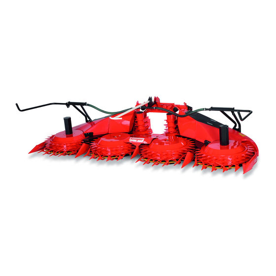
- Page 1 StalkBuster™ Rotary Harvesting Unit OPERATOR'S MANUAL 460plus StalkBuster™ Rotary Harvesting Unit OMKM128769 ISSUE E1 (ENGLISH) Maschinenfabrik Kemper GmbH & Co. KG European Editions PRINTED IN U.S.A.
- Page 2 Use in any other way is considered as contrary to the other languages. To order, see your KEMPER dealer. intended use. The manufacturer accepts no liability for THIS MANUAL SHOULD BE CONSIDERED a permanent...
-
Page 3: Table Of Contents
Contents Page Page Predelivery Inspection Stay Clear of Rotary Harvesting Unit....10-4 Predelivery Checklist ........CLIST-1 Rotating Drums...........10-5 Delivery Checklist .........CLIST-1 Foldable Frame ..........10-5 After-Sale Checklist ........CLIST-1 Input Transmission ..........10-6 Identification View Haulage Identification View..........00-1 Loading with a Crane..........15-1 Secure the Rotary Harvesting Unit for Safety Transport (Lashing Points) ......15-3 Recognize Safety Information ......05-1... - Page 4 Support Wheel)........40-1 Mixing Lubricants..........60-3 Driving on Public Roads (Rotary Lubricant Storage ..........60-3 Harvesting Units with Comfort Use Genuine KEMPER Parts ......60-3 Support Wheel) ..........40-2 Releasing Pneumatic Pressure from Driving on Public Roads (Rotary the StalkBuster™ Units ........60-4 Harvesting Units without Comfort At the Start of Every Harvesting Season ....60-4...
- Page 5 Contents Page Installing Articulated StalkBuster™ Rotors (Option)..........65-8 Adjusting Gatherer Points.........65-10 Checking Scrapers Adjustment ......65-10 Checking and Adjusting Cleaners ....65-11 Cleaning Rotary Harvesting Unit ......65-12 Storage Storage at End of Harvesting Season ....70-1 Start of New Season...........70-1 Technical Specifications Machine Design Life ...........75-1 plus StalkBuster™...
- Page 6 Contents 061721 PN=4...
-
Page 7: Predelivery Inspection
Predelivery Inspection Predelivery Checklist After the rotary harvesting unit has been completely □ All the gear cases have been filled with the correct assembled, inspect it to be sure it is in good running order quantity of the correct oil/grease/coolant (see Lubrication before delivering it to the customer. -
Page 8: Identification View
Identification View Identification View 460plus StalkBuster™ Rotary Harvesting Unit KM00321,0000A74 -19-12MAY20-1/1 00-1 061721 PN=8... -
Page 9: Safety
Replacement safety signs are available from your KEMPER dealer. Before you start working with the machine, learn how to operate the machine and how to use controls properly. Do not let anyone operate without instruction. -
Page 10: Observe Road Traffic Regulations
Safety Observe Road Traffic Regulations Always observe local road traffic regulations when using public roads. FX,ROAD -19-01MAY91-1/1 Operator Ability and/or controls, and operating the machine properly and safely. • Machine owners must make sure that operators • Never allow a child or an untrained person to operate are responsible, trained, have read the operating the machine. -
Page 11: Prepare For Emergencies
Safety Prepare for Emergencies Be prepared if a fire starts. Keep a first aid kit and fire extinguisher handy. Keep emergency numbers for doctors, ambulance service, hospital, and fire department near your telephone. DX,FIRE2 -19-03MAR93-1/1 Wear Protective Clothing Wear close fitting clothing and safety equipment appropriate to the job. -
Page 12: Stay Clear Of Harvesting Unit
Safety Stay Clear of Harvesting Unit Due to their function, the cutting rotors as well as gathering, cross and feed drums cannot be completely shielded. Stay clear of these moving elements during operation. Always disengage main clutch, shut off engine and remove key before servicing or unclogging harvesting unit. -
Page 13: Practice Safe Maintenance
Safety Practice Safe Maintenance Understand service procedure before doing work. Keep area clean and dry. Never lubricate, service, or adjust machine while it is moving. Keep hands, feet, and clothing away from power-driven parts. Disengage all power and operate controls to relieve pressure. Lower equipment to the ground. -
Page 14: Service Machines Safely
Safety Service Machines Safely Tie long hair behind your head. Do not wear a necktie, scarf, loose clothing, or necklace when you work near machine tools or moving parts. If these items were to get caught, severe injury could result. Remove rings and other jewelry to prevent electrical shorts and entanglement in moving parts. -
Page 15: Avoid High-Pressure Fluids
Safety Avoid High-Pressure Fluids Escaping oil under pressure can have sufficient pressure to penetrate the skin, causing serious personal injury. Avoid the hazard by relieving pressure before disconnecting hydraulic or other lines. Check and tighten all connections before applying pressure. Hydraulic oil escaping from pin-holes is difficult to detect, so use a piece of cardboard to search for leaks. -
Page 16: Remove Paint Before Welding Or Heating
Avoid High-Pressure Jet on Safety Decals The water jet can remove or damage safety decals. Avoid to direct the water jet on safety decals. Immediately replace missing or damaged safety decals. Replacement safety decals are available from your KEMPER dealer. CC1021545 KM00321,0000A78 -19-13MAY20-1/1 05-8 061721... -
Page 17: Decommissioning: Proper Recycling And Disposal Of Fluids And Components
• Contact your local environmental or recycling center, or fluids. Do not use food or beverage containers. your KEMPER dealer for information on the proper way • Do not pour waste fluids onto the ground, down a drain, to recycle or dispose of waste. -
Page 18: Park Machine Safely
Safety Park Machine Safely Before working on the machine: • Lower all equipment to the ground. • Stop the engine and remove the key. • Disconnect the battery ground strap. • Hang a "DO NOT OPERATE" tag in operator station. DX,PARK -19-04JUN90-1/1 05-10 061721... -
Page 19: Safety Decals
Safety Decals Pictorial Safety Signs At several important places of this machine safety signs are affixed intended to signify potential danger. The hazard is identified by a pictorial in a warning triangle. An adjacent pictorial provides information how to avoid personal injury. -
Page 20: Repair And Maintenance
Safety Decals Repair and Maintenance Before carrying out adjustment, repair and maintenance work, shut off forage harvester engine and remove ignition key. KM00321,0000945 -19-26APR19-1/1 Rotating Blades Do not touch any moving machine parts. Wait until all moving parts have stopped. The rotating blades are not immediately stopped when the machine is shut down. -
Page 21: Accumulator - Stalkbuster™ Mulching Units
Safety Decals StalkBuster™ mulching units are pivoting by pneumatic pressure. Never reach into crushing danger area as long as the StalkBuster™ mulching units pivot. Before carrying out adjustment, repair and maintenance work, release pneumatic pressure. KM00321,0000A7A -19-13MAY20-2/2 Accumulator - StalkBuster™ Mulching Units Avoid bodily injuries from air under pressure. -
Page 22: Folding Area
Safety Decals Folding Area Stay clear of the folding area of the rotary harvesting unit. When folding or unfolding the rotary harvesting unit, ensure that no persons are standing within the folding area. Before folding or unfolding, ensure that all persons keep the required safety distance from the rotary harvesting unit. -
Page 23: Rotating Drums
Safety Decals Rotating Drums Stay clear of rotating drums to avoid personal injury. Arms, legs or loose clothing might become caught by the rotating drums when in operation. Always keep the required safety distance from the rotating drums. Wait until all moving parts have stopped. KM00321,000094A -19-26APR19-1/1 Foldable Frame Never reach into the crushing danger area as long as the... -
Page 24: Input Transmission
Safety Decals Input Transmission Input transmission can cause excessive heat. Stay clear of hot surface. Hot surface can cause serious burns. KM00321,000094C -19-26APR19-1/1 10-6 061721 PN=24... -
Page 25: Haulage
Haulage Loading with a Crane Lifting the Header With a Traverse A—Chains B—Chains C—Traverse The chains (A) and (B) must be pulled upwards vertically. CAUTION: When loading the rotary harvesting unit Therefore, use a traverse (C). with a crane, always use the suspension points. This prevents the machine from toppling over. - Page 26 This kit is mandatory and consists of two heavy-duty lifting eye nuts (A). NOTE: The kit is available through spare parts channel. Contact your Kemper dealer. 1. Remove the existing lifting eye nuts in the two center gathering drums and install the heavy-duty lifting eye nuts (A).
-
Page 27: Secure The Rotary Harvesting Unit For Transport (Lashing Points)
Haulage Secure the Rotary Harvesting Unit for Transport (Lashing Points) Lashing Points Lashing Points A—Tensioner Belts Continued on next page KM00321,00006E3 -19-24OCT17-1/2 15-3 061721 PN=27... - Page 28 Haulage Secure rotary harvesting unit with tensioner belts (A) on both sides as shown. Secure accessories with an additional tensioner belt (optional). KM00321,00006E3 -19-24OCT17-2/2 15-4 061721 PN=28...
-
Page 29: Preparing The Rotary Harvesting Unit
Preparing the Rotary Harvesting Unit Unpacking As soon as packaging material is removed, check the unit for any damage that might have been incurred during transport. KM00321,0000038 -19-01SEP08-1/1 Working Under a Raised Rotary Harvesting Unit CAUTION: Before working under a raised rotary harvesting unit, secure the cutterhead against unintentional lowering. -
Page 30: Removing The Transport Pallet
Preparing the Rotary Harvesting Unit Removing the Transport Pallet 1. Remove the transport straps (A). 2. Lift the rotary harvesting unit. IMPORTANT: To secure the rotary harvesting unit against lowering, perform the steps as described under "Working under a Raised Rotary Harvesting Unit"... -
Page 31: Set Outer Protective Covers Into Operating Position
Preparing the Rotary Harvesting Unit Set Outer Protective Covers into Operating Position NOTE: The two outer protective covers (A) are folded up for transport purposes. 1. Remove screw (B). 2. Fold the outer protective cover (A) down in the direction of the arrow into the operating position. A—Protective Cover B—Screw Transport Position... -
Page 32: Adjusting The Height Of Scraper Sheets On The Center Stalkbuster™ Mulching Units
Preparing the Rotary Harvesting Unit Adjusting the Height of Scraper Sheets on the Center StalkBuster™ Mulching Units NOTE: For transport reasons, the scraper sheets (A) on the center StalkBuster™ mulching units are set to the highest position. After the transport pallet has been removed, the scraper sheets (A) must be adjusted. -
Page 33: Adjusting The Inner Skid Shoes
Preparing the Rotary Harvesting Unit Adjusting the Inner Skid Shoes IMPORTANT: The inner skid shoes (A) must be adjusted before the first use. The skid shoes (A) can be set in two positions (see arrows). Adjust the inner skid shoes: CAUTION: Secure the rotary harvesting unit against unintentional lowering. -
Page 34: Attaching To A Claas Forage Harvester
Attaching to a CLAAS Forage Harvester Compatibility Chart steps included in Section Preparing the Rotary Harvesting Unit. CAUTION: Before attaching the rotary harvesting The rotary harvesting unit is prepared for installation on unit to a forage harvester, carry out the the following CLAAS forage harvester types: Rotary harvesting unit/CLAAS forage harvester compatibility chart .............. -
Page 35: Attaching To A Type 502 Forage Harvester With Variable Header Drive
4. When entering a serial number, enter released by Claas. IMPORTANT: Enter a serial number of a rotary harvesting unit that corresponds to the working width of the Kemper rotary harvesting unit. Continued on next page KM00321,0000AB5 -19-06MAY21-2/5 30-2 061721... - Page 36 Attaching to a CLAAS Forage Harvester IMPORTANT: The following entries must be released by Claas. 5. Use the old Orbis types when selecting the type of machine. NOTE: For example, in the case of an Orbis 900, select type 992 and not type I53 (see illustration). 6.
- Page 37 Attaching to a CLAAS Forage Harvester A—Adapter Cable B—Main Wiring Harness Connector IMPORTANT: Perform this step only for rotary 8. The adapter cable (A) must be removed from the harvesting units that have been equipped for Claas control unit (C) when the programming is attachment of a support wheel at the factory.
-
Page 38: Installing Additional Wiring Harness For The Folding Function Of The Rotary Harvesting Unit
Attaching to a CLAAS Forage Harvester Installing Additional Wiring Harness for the Folding Function of the Rotary Harvesting Unit IMPORTANT: The additional wiring harness is supplied with the following rotary harvesting units and must be mounted on the forage harvester: •... - Page 39 Attaching to a CLAAS Forage Harvester 3. Install the socket outlet (A) on the Claas forage harvester with screws (B). NOTE: The mounting position of the socket outlet varies and depends on the model of the forage harvester. A—Socket Outlet B—Screws Mounting position of the socket outlet Mounting position of the socket outlet...
- Page 40 Attaching to a CLAAS Forage Harvester 4. Fix the remaining cables with cable binders (A) behind the front cover. 5. Plug the connection cable (B) into the socket outlet and connect it to the main wiring harness (C). NOTE: The socket outlet may be mounted on the forage harvester after the corn harvest.
-
Page 41: Installing Additional Wiring Harness For The Stalkbuster™ Function
Attaching to a CLAAS Forage Harvester Installing Additional Wiring Harness for the StalkBuster™ function NOTE: To control the lifting and lowering of the StalkBuster™ mulching units, the signal of the external additive plant is used. The supplied wiring harness with the socket outlet (A) must be installed for this purpose. - Page 42 Attaching to a CLAAS Forage Harvester 3. Fix the cable (A) with cable binders behind the front cover and route it to behind the operator's cab. A—Cable KM00321,0000AB7 -19-11MAY21-2/3 4. Open the right side cover on the forage harvester. 5. Connect the wiring harness to the 2-pin connector with the labeling "ZX".
-
Page 43: Attaching To Claas Forage Harvesters
Attaching to a CLAAS Forage Harvester Attaching to CLAAS Forage Harvesters 1. Drive the forage harvester close to the rotary harvesting unit's frame until latching hooks (A) protrude into brackets (D) of the mounting frame. 2. Remove pins (C) on both sides. 3. -
Page 44: Connecting The Electrical Connectors To The Forage Harvester
Attaching to a CLAAS Forage Harvester 5. At left and right, remove the jackstands (A) from the front of the machine and store them in the holders (B) provided at the outer feed bars. A—Jackstand B—Holder KM00321,0000BAE -19-10MAY21-2/2 Connecting the Electrical Connectors to the Forage Harvester Connect the 13-pole connector (A) to the socket on the forage harvester. -
Page 45: Rotary Harvesting Units With Multi-Speed Gearbox And Quick Coupler
Attaching to a CLAAS Forage Harvester Rotary Harvesting Units with Multi-Speed Gearbox and Quick Coupler Adjust the quick coupler (only for initial use) 1. Make sure that attaching claw (A) on the rotary harvesting unit and attaching claw (B) on the forage harvester are in alignment. -
Page 46: Detaching The Rotary Harvesting Unit
Attaching to a CLAAS Forage Harvester Detaching the Rotary Harvesting Unit IMPORTANT: Before detaching the rotary harvesting unit, make sure that rotary harvesting unit hydraulic functions are all released. Follow the instructions below: 1. Disconnect all plug connections from the forage harvester. - Page 47 Attaching to a CLAAS Forage Harvester 4. Remove pin (A). A—Pin KM00321,0000BAF -19-10MAY21-4/5 5. Lower the front shield of the forage harvester and move it out of the mounting frame of the rotary harvesting unit. KM00321,0000BAF -19-10MAY21-5/5 30-14 061721 PN=47...
-
Page 48: Attaching To A Fendt Forage Harvester
Attaching to a FENDT Forage Harvester Align the Oscillating Frame Align oscillating frame (A) with linear module (B). A—Oscillating Frame B—Linear Module KM00321,0000A81 -19-13MAY20-1/1 Attach the Rotary Harvesting Unit to FENDT Forage Harvesters 1. Use tensioning lever (A) to open the lock. A—Tensioning Lever KM00321,0000A82 -19-14MAY20-1/8 2. - Page 49 Attaching to a FENDT Forage Harvester 3. Raise the lifting gear until pins (B) engage in the lower latches (A) at left and right. 4. Stop the engine. 5. Apply the park brake. A—Latches B—Pin KM00321,0000A82 -19-14MAY20-3/8 6. Use tensioning lever (A) to close the lock. A—Tensioning Lever KM00321,0000A82 -19-14MAY20-4/8 7.
- Page 50 Attaching to a FENDT Forage Harvester 8. At left and right, raise jackstand (A) to the same height as protective tube (C). 9. Secure jackstand (A) with spring-loaded pin (B). A—Jackstand C—Protective Tube B—Spring-Loaded Pin KM00321,0000A82 -19-14MAY20-6/8 10. Connect the pneumatic hose to the outlet (A). A—Outlet KM00321,0000A82 -19-14MAY20-7/8 11.
-
Page 51: Driveline
Attaching to a FENDT Forage Harvester Driveline A—Driveline C—Forage Harvester End B—Header End KM00321,0000A83 -19-14MAY20-1/1 Connect Driveline 1. Press sliding pin (A) and slide the joint onto the splined shaft on the rotary harvesting unit until sliding pin (A) engages in the ring-shaped groove. A—Sliding Pin KM00321,0000A84 -19-14MAY20-1/3 2. -
Page 52: Change The Hydraulic System
Attaching to a FENDT Forage Harvester 3. Press sliding pin (A) and slide the joint onto the splined shaft on the forage harvester until sliding pin (A) engages in the ring-shaped groove. A—Sliding Pin KM00321,0000A84 -19-14MAY20-3/3 Change the Hydraulic System Move ball cock (A) to position for the relevant header. -
Page 53: Unlock The Oscillating Frame
Attaching to a FENDT Forage Harvester Unlock the Oscillating Frame Remove locking pin (A) and insert it in hole (B) in the oscillating frame. NOTE: The oscillating frame is now unlocked. A—Locking Pin B—Hole KM00321,0000A86 -19-14MAY20-1/1 Detaching the Rotary Harvesting Unit NOTE: Fold the rotary harvesting unit before setting it down. -
Page 54: Transport
Transport Transport Information government regulations when driving harvester on public road. CAUTION: When driving on public roads or Depending on local road regulations, the use of highways at night or during the day, observe local the comfort support wheel might be mandatory. traffic regulations regarding warning devices, lighting and safety. -
Page 55: Driving On Public Roads (Rotary Harvesting Units With Comfort Support Wheel)
Transport Driving on Public Roads (Rotary Harvesting Units with Comfort Support Wheel) A—Protective curtains B—Position Lamps/Turning C—Support wheel Lights IMPORTANT: Rotary harvesting units equipped for Position Lamps and Turning Lights: installation of the comfort support wheel (C) may be driven on public roads only if the As the position lamps and turning lights on the forage comfort support wheel is actually attached. -
Page 56: Driving On Public Roads (Rotary Harvesting Units Without Comfort Support Wheel)
Transport Driving on Public Roads (Rotary Harvesting Units without Comfort Support Wheel) When driving on public roads, the entire area around the crop separators must be covered with a protective guard (A). Protective guard (A) assembly sequence: 1. Wait until rotating blades have come to a complete stop. -
Page 57: Operating The Rotary Harvesting Unit
Operating the Rotary Harvesting Unit Method of Operating the Rotary Harvesting Unit A—Gathering Drum D—Lengthwise Direction of Crop F— Feed Teeth B—Gatherer Points E—Feed Drum G—Guides and Scrapers C—Rotating Blade H—Feed Bar It makes no difference to the rotary harvesting unit how it (F) and so the stalks are conveyed along the guides and approaches the crop - it can operate along the rows, across scrapers (G) to the feed drums (E). -
Page 58: Operating The Rotary Harvesting Unit - General Use
Operating the Rotary Harvesting Unit Operating the Rotary Harvesting Unit - Operating the Rotary Harvesting Unit General Use Once the cutterhead is turning at the correct speed, and Starting the Forage Harvester the rotary cutters are at the appropriate speed, drive into the standing crop. -
Page 59: Adjusting The Central Feed Bar
Operating the Rotary Harvesting Unit Adjusting the Central Feed Bar NOTE: If crop is short, set central feed bar (A) low. Feed bars (A) and (B) force the crop inward and assure a better feed. The height of the central feed bar (A) can be altered in the field to suit the prevailing crop conditions. -
Page 60: Adjusting The Skid Shoes
Operating the Rotary Harvesting Unit Adjusting the Skid Shoes CAUTION: Secure the rotary harvesting unit against unintentional lowering. See "Working Under a Raised Rotary Harvesting Unit" in "Preparing the Rotary Harvesting Unit" section. Outer skid shoes (A) and inner skid shoes (B) can be set in two positions (see arrows). -
Page 61: Stalkbuster™ Mulching Units - Theory Of Operation
Operating the Rotary Harvesting Unit StalkBuster™ mulching units – theory of operation Eight integrated rotary mulching units (A) in the main frame of the header destroy the stubble from the top to the bottom to prevent corn borer infestation. No stubble are flattened by the tires of the forage harvester or tractors. - Page 62 Operating the Rotary Harvesting Unit The StalkBuster™ mulching units (A) are raised into park position or lowered into operating position by pneumatic pressure. A—StalkBuster™ Mulching Unit Park Position Operating Position KM00321,0000BA6 -19-06MAY21-2/2 45-6 061721 PN=62...
-
Page 63: Adjust The Height Of Stalkbuster™ Scraper Sheets
Operating the Rotary Harvesting Unit Adjust the Height of StalkBuster™ Scraper Sheets The height of the scraper sheets (A) can be adjusted via the oblong holes. This setting affects the working height of the rotors. 1. Starting with the scraper plates (A) in position (1) is recommended. -
Page 64: Activate The Stalkbuster™ Function On Fendt Forage Harvesters
Operating the Rotary Harvesting Unit Activate the StalkBuster™ Function on FENDT Forage Harvesters 1— Softkey 3— Softkey 2— Softkey A—Selection Point "StalkBuster Existing" 1. Press softkeys (1), (2) and (3) to access the header 2. Choose "available" at the selection point "StalkBuster settings page. - Page 65 Operating the Rotary Harvesting Unit 1— Softkey B—Minimum Ground Speed D—Trigger Point for Lowering the 2— Softkey C—Manual Lift Button Mulching Units 3— Softkey A—Additional Header Settings Page 3. Press softkey (3) to access the additional header NOTE: It is also possible to lift the Stalkbuster™ mulching settings page (A).
-
Page 66: Activating The Stalkbuster™ Function On Claas Forage Harvesters
Operating the Rotary Harvesting Unit Activating the StalkBuster™ Function on Claas Forage Harvesters Turn on the switch for the additive plant on the hand console (A). NOTE: To control the lifting and lowering of the StalkBuster™ mulching units, the signal of the additive plant is used. -
Page 67: Harvesting With Deactivated Stalkbuster™ Function
Insert a screw M16 X 70 (B) to protect the thread from dirt. NOTE: To protect the gear case flange (D), a cap (C) is available through spare parts channel. Contact your Kemper dealer. IMPORTANT: Maintain pneumatic pressure to ensure that the StalkBuster™ mulching units are raised in park position. -
Page 68: Adjusting Gear Selection With Multi-Speed Gearbox For Claas Forage Harvesters
Operating the Rotary Harvesting Unit Adjusting Gear Selection with Multi-Speed Gearbox for CLAAS Forage Harvesters The multi-speed drive for CLAAS forage harvesters has 4 speeds. The first 2 speeds are selected by turning nut (B) on the outside of the drive. The entire multi-speed drive can be rotated so that 2 more speeds (A) can be selected. -
Page 69: Lengths Of Cut And Gear Selection With Multi-Speed Gearbox For Claas Forage Harvesters
Operating the Rotary Harvesting Unit 3. Rotate drive (C) through 180°. NOTE: The gearbox can be rotated without taking it off. 4. Tighten hex socket screws (D) to specification. Specification Gearbox, Hex Socket Screws—Torque............95 N·m (70 lb.-ft.) 5. Re-install universal-jointed shaft (E) and shield (F). C—Gearbox E—Universal-Jointed Shaft D—Hex Socket Screws... -
Page 70: Harvesting
Operating the Rotary Harvesting Unit Harvesting Before the harvest, do the following: - Unfold the rotary harvesting unit - Check that the rotary cutter brakes are functioning properly - Adjust the feed bars - Adjust the speed at which the gathering drums operate IMPORTANT: Avoid unnecessary wear at the clutches. -
Page 71: Accessories
Accessories Special Kit for Row Guidance (Steering • (1) sensor system with connecting cables Assistance) • (1) set of hardware for installation on rotary harvesting unit When driving a forage harvester 90% of the driver's • (1) assembly instructions attention is focused on steering. Use of the entire machine capacities is thus only possible with assisted steering. -
Page 72: Troubleshooting
Poor cut with widely spaced rows The unit is tackling seven rows of Tackle only six rows of plants. Contact plants. The middle row is hindering your KEMPER dealer if necessary. the cut. Continued on next page KM00321,0000ABE -19-16JUN20-1/2 55-1... - Page 73 Troubleshooting Symptom Problem Solution StalkBuster™ units refuse to Pneumatic pressure supply Restore pneumatic pressure supply raise/lower interrupted Solenoid of the valves is stuck Replace the valves Electrical connection of the valves Check and repair electrical connection failed StalkBuster™ units vibrate Rotors are unbalanced Replace rotors Covers are loose...
-
Page 74: Lubrication And Periodic Service
Lubrication and Periodic Service Service Intervals IMPORTANT: Replace any damaged parts. Any screws that have worked loose must be CAUTION: Before making any adjustments or retightened to the proper torque. doing any service work, always: - Switch the machine off Clean grease fittings before lubrication. -
Page 75: Transmission Oil
A 50% mixture of ethylene coolant in water provides coolant. freeze protection to -37°C (-34°F). If protection at lower temperatures is required, consult your KEMPER dealer for recommendations. KM00321,0000A95 -19-15MAY20-1/1 60-2... -
Page 76: Alternative And Synthetic Lubricants
Other parts are neither examined nor released by KEMPER. Installation and use of such products could have negative effects upon the design characteristics of KEMPER machines and thereby affect their safety. Avoid this risk by using only genuine KEMPER parts. KM00321,0000A98 -19-15MAY20-1/1 60-3 061721... -
Page 77: Releasing Pneumatic Pressure From The Stalkbuster™ Units
Lubrication and Periodic Service Releasing Pneumatic Pressure from the StalkBuster™ Units CAUTION: Before carrying out adjustment, repair and maintenance work, release the pneumatic pressure from the StalkBuster™ units. 1. Turn the knob (A) at the control valve (B) clockwise to release the pneumatic pressure. -
Page 78: At The Start Of Every Harvesting Season-Spherical Collar Bolts
Lubrication and Periodic Service At the Start of Every Harvesting Season—Spherical Collar Bolts The torques of the spherical collar bolts (A) must be checked prior to each harvesting season and adjusted where necessary. The torque setting is: Specification Spherical Collar Bolts—Torque............. -
Page 79: At The Start Of Every Harvesting Season-Gearbox Mounting Flange Attaching Screws
Lubrication and Periodic Service At the Start of Every Harvesting Season—Gearbox Mounting Flange Attaching Screws The torques of the flange screws (A) at gearbox mounting flanges of gathering drums must be retighten prior to each harvesting season and then retighten after 50 hours in service. -
Page 80: Overview Of Transmissions And Oil Levels
Lubrication and Periodic Service Overview of Transmissions and Oil Levels A—Oil Drain Plug 2— Angle Drive - 1.5 L (0.4 US. 4— Spur Gear Angle Drive - 1.1 L B—Oil Filler Plug gal.) (0.29 US. gal.) C—Breather 3— Feed Drum Spur Gear Angle 5—... -
Page 81: Overview Of The Oil Levels In The Claas Multi-Speed Gearbox
Lubrication and Periodic Service Overview of the Oil Levels in the Claas Multi-speed Gearbox A—Bevel Gear Drive for B—4-gear Multi-speed Gearbox Quick-coupler - 1.2 L (0.31 - 1.25 L (0.33 U.S. gal.) U.S. gal.) KM00321,0000ABF -19-16JUN20-1/1 Oil Hand Pump for the Oil Change in StalkBuster™... -
Page 82: Changing Oil In Stalkbuster™ Transmissions
Lubrication and Periodic Service Changing Oil in StalkBuster™ Transmissions Drain oil IMPORTANT: The oil in the StalkBuster™ transmissions must be changed after the first 50 operating hours and then every 500 operating hours. 1. Unfold the rotary harvesting unit. 2. Loosen the screw (A) and remove the rotor (B). IMPORTANT: Before removing the drain screw (D), make sure that the hex socket wrench is in a good condition to prevent damage to the... - Page 83 Lubrication and Periodic Service 2. Screw the adapter (A) of the oil hand pump (B) into the thread of the oil drain screw. 3. To activate the transmission ventilation, first pump 400 mL (13.6 oz) of oil into the gear case using the oil hand pump (B).
-
Page 84: Every 10 Hours-Check And Clean
Lubrication and Periodic Service 5. Attach thread sealing tape to the drain screw (A). 6. Remove the oil hand pump and then reinstall drain screw (A) immediately to prevent oil loss. 7. Tighten drain screw (A) to specification. Specification Drain screw—Torque............. 10 N·m (7.4 lb-ft) 8. - Page 85 Lubrication and Periodic Service 2. Check and clean the area between the square tube of the base frame and the covers of the StalkBuster™ mulching units. KM00321,0000A9C -19-15MAY20-2/5 3. Check and clean the area between the rotors and the covers of the StalkBuster™ mulching units. KM00321,0000A9C -19-15MAY20-3/5 4.
-
Page 86: Every 10 Hours-Cleaners And Blade Rotor Segments
Lubrication and Periodic Service 5. Check and clean the area behind the feeler of the steering sensor. KM00321,0000A9C -19-15MAY20-5/5 Every 10 Hours—Cleaners and Blade Rotor Segments Check all cleaners (A) and blade rotor segments (B) for signs of wear. Replace worn parts (see "Service" section). A—Cleaner B—Blade Rotor Segment KM00321,00006F3 -19-03NOV17-1/1... -
Page 87: Every 10 Hours-Drive Shaft
Lubrication and Periodic Service Every 10 Hours—Drive Shaft Lubricate with grease. KM00321,0000A9D -19-15MAY20-1/1 Every 10 Hours—StalkBuster™ Control Valve Turn reservoir (A) in direction of arrow. Remove reservoir (A) from the control valve. Clean and reinstall reservoir (A). A—Reservoir KM00321,0000A6F -19-08MAY20-1/1 60-14 061721 PN=87... -
Page 88: Every 10 Hours-Stalkbuster™ Accumulators
Lubrication and Periodic Service Every 10 Hours—StalkBuster™ Accumulators Pull ring (A) and drain condensation. A—Ring KM00321,0000963 -19-31MAY19-1/1 Every 50 Hours—Claw Clutch Clean all the claw clutches (see arrows). Lubricate with grease. Apply also a layer of grease to the grooved surface of the clutch claws using a brush. -
Page 89: Every 50 Hours-Lower Pin Of Hydraulic Cylinder And Hinges Of The Outer Units
Lubrication and Periodic Service Every 50 Hours—Lower Pin of Hydraulic Cylinder and Hinges of the Outer Units Lubricate with grease. KM00321,0000A9F -19-15MAY20-1/1 Annually—Check and Clean 1. Take off cover (A). 2. Clean the area around the breather behind the cover (A). -
Page 90: Every 3 Years-Change Coolant Of Main Drive Friction Clutch
The cavity of the friction clutch (A) can be drained and refilled. This service work requires the friction clutch to be removed from the machine. Therefore it is advised to contact your KEMPER dealer to drain/refill the friction clutch. Specification Main drive friction clutch cavity—Capacity ............ -
Page 91: After Each Harvesting Season
After Each Harvesting Season • Clean the entire rotary harvesting unit - pay particular from your KEMPER dealer, so that they can be installed attention to the depressions (A) in the gathering drums. in time for the next harvesting season. -
Page 92: Service
Service Metric Bolt and Screw Torque Values TS1742 —UN—31MAY18 10.9 12.9 12.9 10.9 Class 4.8 Class 8.8 or 9.8 Class 10.9 Class 12.9 Bolt or Screw Hex Head Flange Hex Head Flange Hex Head Flange Hex Head Flange Size Head Head Head Head... -
Page 93: Releasing Pneumatic Pressure From The Stalkbuster™ Units
Service Releasing Pneumatic Pressure from the StalkBuster™ Units CAUTION: Before carrying out adjustment, repair and maintenance work, release the pneumatic pressure from the StalkBuster™ units. 1. Turn the knob (A) at the control valve (B) clockwise to release the pneumatic pressure. NOTE: The control valve (B) is located on the right-hand side of the header (viewed in direction of travel). -
Page 94: Relieving Pressure At The Slip Clutches On The Main Drive
4. Unscrew screws (C) as far as their threads allow (without removing them completely). 5. Install cover (A), bolting it down with screws (B). IMPORTANT: We recommend that you have the slip clutches checked by your Kemper dealer once every year. KM00321,0000AA2 -19-15MAY20-2/2 65-3... -
Page 95: Disassemble Slip Clutch
Service Disassemble Slip Clutch If it is not possible to turn slip clutch by hand as explained under ”Relieving Pressure at the Slip Clutches on the Main Drive”, it has to be disassembled and cleaned for proper function. Proceed as follows: 1. -
Page 96: Installing New Rotating Blades
Service Installing New Rotating Blades A—Yellow Blade D—Cleaner (Counter-Clockwise) F— Reinforcement Strap B—Black Blade E—Cleaner (Clockwise) G—Direction of Cut C—Strap - 4 yellow blades (A), and CAUTION: Before making any adjustments or - 4 black blades (B) doing any service work, always: 2. - Page 97 Service NOTE: Install cleaners (D) and (E) with their cutting edges facing in the direction of cut. KM00321,0000967 -19-04JUN19-2/3 Tighten all attaching screws of blade segments and cleaners with the specified torque. Specification M8 Screws—Torque..............28 N·m 20.65 lb.-ft. M10 Screws—Torque..............51 N·m 37.62 lb.-ft.
-
Page 98: Installing Rigid Stalkbuster™ Rotors
Service Installing Rigid StalkBuster™ Rotors 1. Loosen screw (A) and remove rotor (B). 2. Install a new rotor. 3. Secure rotors against each other by using a tube (C) with an inner diameter of 60 mm (2.36 in). 4. Tighten hex socket screw to specification. Specification Hex socket screw—Torque............ -
Page 99: Continued On Next Page
Service Installing Articulated StalkBuster™ Rotors (Option) 1. Loosen cap screw (A) and remove rotor (B). 2. Install a new rotor. NOTE: The rotors on the left and right are different. Pin (C) prevents incorrect assembly. 3. Secure the rotor against twisting by using a tube (D) with an inner diameter of at least 60 mm (2.36 in). - Page 100 Service Replacing the Impeller Vane 1. Loosen the hex socket screws (B) and remove the impeller vane (A). 2. Check hex socket screws (B) and bushing (C) for signs of wear. Replace as required. 3. Install a new impeller vane. 4.
-
Page 101: Adjusting Gatherer Points
Service Adjusting Gatherer Points In order to prevent plugging and crop losses, the gatherer points (A) have to be properly adjusted. Always keep distance (X) between 3 and 7 mm (0.12 and 0.27 in.). The specified distance (X) can be adjusted by means of two slot holes (see arrows). -
Page 102: Checking And Adjusting Cleaners
Service Checking and Adjusting Cleaners Check adjustment and condition of the cleaners (A) frequently, replace if necessary. Damaged or wrongly adjusted cleaners unnecessarily burden the drive and may cause malfunction of the rotary harvesting unit. Set cleaner (A) as close as possible to the scraper (B) by bending up cleaner (A). -
Page 103: Cleaning Rotary Harvesting Unit
Service Cleaning Rotary Harvesting Unit Remove loose crop by means of compressed air and/or a hand brush. When using high pressure/steam cleaners, keep a minimum distance (X) of 250 mm (9.84 in.). Refer to specifications for the maximum temperature and maximum pressure. -
Page 104: Storage
• Check the rotary harvesting unit for damaged or worn parts and replace them as necessary. For more detailed checks, see your KEMPER dealer. • Touch up the paintwork if required, and clean the decals. KM00321,0000AA3 -19-15MAY20-1/1 Start of New Season •... -
Page 105: Technical Specifications
All missing or damaged safety-related components, including safety Periodically inspect and review the machine in conjunction signs, should be repaired or replaced before operating. with your Kemper dealer. The review may result in recommendations for service, component repair, KM00321,0000AA5 -19-15MAY20-1/1 plus StalkBuster™... -
Page 106: Ec Declaration Of Conformity
Technical Specifications EC Declaration of Conformity Maschinenfabrik Kemper GmbH & Co. KG Breul D-48703 Stadtlohn, Germany The person named below declares that Machine type: Rotary Harvesting Unit plus Model: 460 StalkBuster™ fulfills all relevant provisions and essential requirements of the following directives:... -
Page 107: Serial Number
Serial Number Rotary Harvesting Unit Serial Number Plate A—Type D—Weight B—Model designation E—Year of construction C—Product identification F— Model year number KM00321,0000AA7 -19-15MAY20-1/1 Serial Number When ordering parts, always quote the rotary harvesting unit serial number. The serial number is located on the right-hand side of the attaching frame. - Page 108 Serial Number 80-2 061721 PN=108...
- Page 109 Index Page Page Alternative lubricants ..........60-3 Attaching Gatherer Points Attaching to CLAAS Forage Harvesters ....30-10 Adjusting ............... 65-10 Rotary Harvesting Units with Grease Multi-Speed Gearbox and Quick Coupler..30-12 Extreme Pressure and Multi-Purpose ..... 60-1 Attaching to Fendt forage harvesters Low-viscosity grease for gears .......
- Page 110 Index Page Page Feed Drum .............. 45-1 Scraper adjustment ..........65-10 Feed Teeth .............. 45-1 Serial number plate ............ 80-1 Gatherer Points............45-1 Signal words, understand ........... 05-1 Gathering Drum ............45-1 Skid Shoes Guides and Scrapers ..........45-1 Adjustment .............. 45-4 Lengthwise Direction of Crop........
- Page 111 Index Index-3 061721 PN=3...
- Page 112 Index Index-4 061721 PN=4...
Need help?
Do you have a question about the StalkBuster 460plus and is the answer not in the manual?
Questions and answers