Table of Contents

Related Manuals for Kemper 345plus


Summary of Contents for Kemper 345plus
- Page 1 Rotary Harvesting Units plus plus plus plus OPERATOR'S MANUAL 345plus, 360plus, 375plus, and 390plus Rotary Harvesting Units OMKM122361 ISSUE B9 (ENGLISH) Maschinenfabrik Kemper GmbH & Co. KG European Edition PRINTED IN U.S.A.
- Page 2 Use in any other way is considered as contrary to the other languages. To order, see your KEMPER dealer. intended use. The manufacturer accepts no liability for THIS MANUAL SHOULD BE CONSIDERED a permanent...
-
Page 3: Table Of Contents
Pictorial Safety Signs..........10-1 Connecting the Drive (Forage Replace Safety Signs .........10-1 Harvester Type 496)........20-20 Operator's Manual ..........10-1 Replace CLAAS Tray with KEMPER Tray..20-24 Repair and Maintenance ........10-2 Rotating Blades ..........10-2 Attaching to a KRONE Forage Harvester Folding Area ............10-3 Compatibility Chart ..........22-1 Rotating Drums...........10-3... - Page 4 Accident Prevention (Rotary Mixing Lubricants..........50-3 Harvesting Units without Lateral Lubricant Storage ..........50-3 Protective Brackets) ........30-4 Use Genuine KEMPER Parts ......50-3 Set AHC sensors in the transport position..30-6 Overview of Transmissions and Oil Lock/Unlock Tilt Frame (Rotary Levels (Part 1)..........50-4 Harvesting Units for CLAAS Forage Overview of Transmissions and Oil Harvesters Only) ..........30-6...
- Page 5 Contents Page Every 50 Hours - Hydraulic Cylinder plus Axle Pins (390 Only)........ 50-11 Every 50 Hours - Upper Rolls of Oscillating Frame ......... 50-11 Every 3 Years—Change Coolant of Main Drive Friction Clutch ......50-12 At the Start of Every Harvesting Season ..50-12 Daily Maintenance (Or More Often if Necessary) ...........50-12 Weekly Service..........50-13...
- Page 6 Contents 031519 PN=4...
-
Page 7: Pre-Delivery Inspection
Pre-delivery Inspection Predelivery Checklist After the rotary harvesting unit has been completely □ Shipping brackets removed. assembled, inspect it to be sure it is in good running order before delivering it to the customer. Check off each item □ Rotary harvesting unit can be folded correctly. when found satisfactory or after making the necessary □... -
Page 8: After-Sale Checklist
Pre-delivery Inspection After-Sale Checklist The following items should be checked sometime during □ Check for worn rotary knives. the first season of operation with the rotary harvesting unit. □ Check with the customer as to the performance of the □ Go over the entire machine for loose or missing nuts rotary harvesting unit thus far. -
Page 9: Identification View
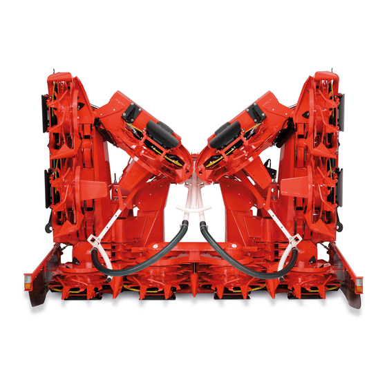
Identification View Identification View plus Rotary Harvesting Unit Shown KM00321,000030D -19-14JUN10-1/1 00-1 031519 PN=9... -
Page 10: Safety Measures
Replacement safety signs are available from your KEMPER dealer. Before you start working with the machine, learn how to operate the machine and how to use controls properly. Do not let anyone operate without instruction. -
Page 11: Observe Road Traffic Regulations
Safety Measures Observe Road Traffic Regulations Always observe local road traffic regulations when using public roads. FX,ROAD -19-01MAY91-1/1 Operator Ability and/or controls, and operating the machine properly and safely. • Machine owners must make sure that operators • Never allow a child or an untrained person to operate are responsible, trained, have read the operating the machine. -
Page 12: Prepare For Emergencies
Safety Measures Prepare for Emergencies Be prepared if a fire starts. Keep a first aid kit and fire extinguisher handy. Keep emergency numbers for doctors, ambulance service, hospital, and fire department near your telephone. DX,FIRE2 -19-03MAR93-1/1 Wear Protective Clothing Wear close fitting clothing and safety equipment appropriate to the job. -
Page 13: Guards And Shields
Safety Measures Guards and Shields Keep guards and shields in place at all times. Ensure that they are serviceable and installed correctly. Always disengage main clutch, shut off engine and remove key before removing any guards or shields. Keep hands, feet and clothing away from moving parts. FX,DEVICE -19-04DEC90-1/1 Stay Clear of Harvesting Unit Due to their function, the cutting rotors as well as gathering,... -
Page 14: Store Attachments Safely
Safety Measures Store Attachments Safely Stored attachments such as dual wheels, cage wheels, and loaders can fall and cause serious injury or death. Securely store attachments and implements to prevent falling. Keep playing children and bystanders away from storage area. DX,STORE -19-03MAR93-1/1 Practice Safe Maintenance Understand service procedure before doing work. -
Page 15: Stay Clear Of Rotating Drivelines
Safety Measures Stay Clear of Rotating Drivelines Entanglement in rotating driveline can cause serious injury or death. Keep all shields in place at all times. Make sure rotating shields turn freely. Wear close-fitting clothing. Stop the engine and be sure that all rotating parts and drivelines are stopped before making adjustments, connections, or performing any type of service on engine or machine driven equipment. -
Page 16: Avoid High-Pressure Fluids
Safety Measures Avoid High-Pressure Fluids Escaping oil under pressure can have sufficient pressure to penetrate the skin, causing serious personal injury. Avoid the hazard by relieving pressure before disconnecting hydraulic or other lines. Check and tighten all connections before applying pressure. Hydraulic oil escaping from pin-holes is difficult to detect, so use a piece of cardboard to search for leaks. -
Page 17: Ballasting For Safe Ground Contact
Dispose of Waste Properly If waste disposal is carried out improperly, this may damage the environment and ecological systems. Potentially harmful waste used with KEMPER equipment include such items as oil, fuel, coolant, brake fluid, filters, and batteries. Use leakproof containers when draining fluids. Do not use food or beverage containers that may mislead someone into drinking from them. -
Page 18: Avoid High-Pressure Jet On Safety Decals
Avoid High-Pressure Jet on Safety Decals The water jet can remove or damage safety decals. Avoid to direct the water jet on safety decals. Immediately replace missing or damaged safety decals. Replacement safety decals are available from your KEMPER dealer. CC1021545 KM00321,00002BB -19-31MAR10-1/1 05-9 031519... -
Page 19: Safety Decals
Safety Decals Pictorial Safety Signs At several important places of this machine safety signs are affixed intended to signify potential danger. The hazard is identified by a pictorial in a warning triangle. An adjacent pictorial provides information how to avoid personal injury. -
Page 20: Repair And Maintenance
Safety Decals Repair and Maintenance Before carrying out repair and maintenance work, shut off engine and remove key. KM00321,00001FC -19-13AUG09-1/1 Rotating Blades Do not touch any moving machine parts. Wait until all moving parts have stopped. The rotating blades are not immediately stopped when the machine is shut down. -
Page 21: Folding Area
Safety Decals Folding Area Stay clear of the folding area of the rotary harvesting unit. When folding or unfolding the rotary harvesting unit, ensure that no persons are standing within the folding area. Before folding or unfolding, ensure that all persons keep the required safety distance from the rotary harvesting unit. -
Page 22: Input Transmission
Safety Decals Input Transmission Stay clear of hot surfaces. KM00321,000018D -19-22JUN12-1/1 10-4 031519 PN=22... -
Page 23: Haulage
Haulage Transport Pallet A—Transport pallet Whenever the rotary harvesting unit is hauled separately on a flatbed carrier, always fit the transport pallet (A) CAUTION: Make sure that fork lift meets the supplied! weight requirements of the rotary harvesting unit (see Specifications Section.) After the transport pallet (A) is fitted, the rotary harvesting unit can be loaded with a fork lift. -
Page 24: Loading With A Crane
Haulage Loading with a Crane NOTE: Remove spiral conveyors (A) for access to the hanging points. When reinstalling spiral conveyors (A), pay attention to the correct installation position. Do not swap spiral conveyors! plus plus Models 375 and 390 must be unfolded to use the hanging points underneath the spiral conveyors (A). -
Page 25: Loading Rotary Harvesting Unit On A Truck Or Trailer
Haulage Loading Rotary Harvesting Unit on a Truck or Trailer A—Transport Pallet B—Rubber Pad • IMPORTANT: When loading the rotary harvesting Place slip-resistant rubber pads (B) under transport unit on a truck or trailer, always use transport pallet (A). • pallet (A) supplied with the machine. -
Page 26: Secure Rotary Harvesting Unit (Lashing Points)
Haulage Secure Rotary Harvesting Unit (Lashing Points) Lashing Points Lashing Points A—Tensioner Straps B—Tensioner Strap Continued on next page KM00321,00002E1 -19-20MAY10-1/2 15-4 031519 PN=26... - Page 27 Haulage Secure the rotary harvesting unit on both sides as shown Secure accessories using an additional tensioner strap (B). using tensioner straps (A). KM00321,00002E1 -19-20MAY10-2/2 15-5 031519 PN=27...
-
Page 28: Attaching To A Claas Forage Harvester
Attaching to a Claas forage harvester Compatibility Chart The chart below gives the compatibility between rotary harvesting unit and forage harvester. Rotary Harvesting Unit/Harvester Compatibility plus ................... 830 Type 492/493 840 Type 492/496 850 Type 492/493/496 860 Type 496 870 Type 492/493/496 890 Type 492/493 900 Type 492/493 930 Type 494/497/498... -
Page 29: Attaching To A Type 498 Forage Harvester With Variable Header Drive
4. When entering a serial number, enter released by Claas. IMPORTANT: Enter a serial number of a rotary harvesting unit that corresponds to the working width of the Kemper rotary harvesting unit. Continued on next page KM00321,0000881 -19-26FEB19-2/4 20-2 031519... - Page 30 6. Select the following settings according to the model of the rotary harvesting unit: Rotary harvesting unit Machine type Transmission Transport system model 345plus Orbis 450 3 speed transmission No transport system 360plus/460plus without Orbis 600 3 speed transmission No transport system...
- Page 31 Attaching to a Claas forage harvester A—Adapter cable C—Claas-control unit B—Main wire harness connector IMPORTANT: Perform this step only for rotary 7. The adapter cable (A) must be removed from the harvesting units that have been equipped for Claas control unit (C) when the programming is attachment of a support wheel at the factory.
-
Page 32: Install Additional Wiring Harness (Only Forage Harvesters Of The Types 498)
Attaching to a Claas forage harvester Install additional wiring harness (only forage harvesters of the types 498) IMPORTANT: The additional wiring harness is supplied with the following rotary harvesting units and must be mounted on the forage harvester: • All rotary harvesting units that are equipped for the attachment of the additional chassis •... - Page 33 Attaching to a Claas forage harvester 3. Install the socket outlet (A) on the Claas forage harvester with screws (B). NOTE: The mounting position of the socket outlet varies and depends on the manufacture year of the forage harvester. A—Socket outlet B—Screws Mounting position of the socket outlet Mounting position of the socket outlet...
-
Page 34: Ballasting Harvester
Attaching to a Claas forage harvester Ballasting Harvester IMPORTANT: Always refer to the information given in Wheels and Ballast Section of the forage Before attaching the rotary harvesting unit, make sure harvester operator's manual. harvester is ballasted correctly. KM00321,0000204 -19-18AUG09-1/1 Adjusting Channel Width Before attaching the rotary harvesting unit to the forage harvester, make sure that the feed plates (A) match with... -
Page 35: Install Feed Plates
Attaching to a Claas forage harvester Install Feed Plates Rotary harvesting units with rigid attaching frame: Depending on the condition of the crop, the rotary harvesting unit can be engaged in two different positions. To guide the rotary harvesting unit flat on the ground, install console (A) on both sides in the front position as shown (factory setting). -
Page 36: Attach To Claas Forage Harvesters (Rotary Harvesting Units With Rigid Attaching Frame)
Attaching to a Claas forage harvester In certain harvesting conditions, console (A) can be installed in the rear position to obtain a larger angle to the ground (see illustration). IMPORTANT: When consoles (A) are installed in the rear position, the long feed plates (C) must be installed. - Page 37 Attaching to a Claas forage harvester 2. Drive the forage harvester close to the rotary harvesting unit's frame until attaching straps (B) protrude into consoles (D) of the attaching frame. Lift feed roll housing (C) up until attaching straps (B) of the rotary harvesting unit lie in the consoles (D).
- Page 38 Attaching to a Claas forage harvester 4. Secure upper bearing point by installing pin (G). G—Pin KM00321,0000546 -19-20JUN16-4/5 5. Lock jackstands (E) on the right and left side in the highest position. To do this, pull out spring-loaded pin (F) and let it re-engage when the jackstand is in its final position.
-
Page 39: Attaching To Claas Forage Harvesters (Rotary Harvesting Units With Oscillating Frame)
Attaching to a Claas forage harvester Attaching to CLAAS Forage Harvesters (Rotary Harvesting Units with Oscillating Frame) 1. Unlatch lever (A). 2. Drive the forage harvester close to the rotary harvesting unit's frame until attaching straps (B) protrude into consoles (D) of the attaching frame. 3. -
Page 40: Rotary Harvesting Units With Multi-Speed Transmission And Quick Coupler
Attaching to a Claas forage harvester Rotary Harvesting Units with Multi-Speed Transmission and Quick Coupler Adjust the quick coupler (only for initial use) 1. Make sure that attaching claw (A) on the rotary harvesting unit and attaching claw (B) on the forage harvester are in alignment. -
Page 41: Connect Hydraulic Hoses
Attaching to a Claas forage harvester plus Only on rotary harvesting units 375 with an attaching frame capable of accepting a support wheel: plus If a 375 rotary harvesting unit equipped with a mounting frame capable of accepting a support wheel is converted to attach the comfort support wheel, then shield (A) must be installed as shown in illustration 1. -
Page 42: Connecting The Drive (Forage Harvester Type 492)
Attaching to a Claas forage harvester Connecting the Drive (Forage Harvester Type 492) 1. Install spacer bushings (A). 2. Extend the equipped shield by attaching plate (B). 3. Install protective cover (C). 4. Connect u.j. shaft (D). IMPORTANT: Secure the u.j. shaft (D) with locking screws on both sides. -
Page 43: Connecting The Drive (Forage Harvester Types 493, 494, 497, And 498)
Attaching to a Claas forage harvester Connecting the Drive (Forage Harvester Types 493, 494, 497, and 498) 1. Completely remove claw clutch (A) from rotary harvesting unit drive. To do this, disassemble items 1 to 11. A—Claw clutch KM00321,0000880 -19-18DEC18-1/9 2. - Page 44 Attaching to a Claas forage harvester 3. First insert universal-jointed shaft into splined bushing (A) of the rotary harvesting unit drive on the forage harvester. A—Splined bushing KM00321,0000880 -19-18DEC18-3/9 4. Secure universal-jointed shaft with bushing (A) and retaining nut (B). A—Bushing B—Retaining nut KM00321,0000880 -19-18DEC18-4/9...
- Page 45 Attaching to a Claas forage harvester 6. Ensure that sliding pin (A) is engaged and that the universal-jointed shaft is secured. A—Sliding pin KM00321,0000880 -19-18DEC18-6/9 Installing the Universal-jointed Shaft Shield (Claas 493, 494 and 497) Install bracket (A). Install the universal-jointed shaft shield (B). A—Bracket E—Washer B—Universal-Jointed shaft...
- Page 46 Attaching to a Claas forage harvester Installing the Universal-jointed Shaft Shield (Claas 498) Fix adapter (A) with flange screws (B). NOTE: Insert washers (C) as needed. A—Adapter C—Washers B—Flange screw Continued on next page KM00321,0000880 -19-18DEC18-8/9 20-19 031519 PN=46...
-
Page 47: Connecting The Drive (Forage Harvester Type 496)
Attaching to a Claas forage harvester Mount holder (A) with hex socket screws. Install the universal-jointed shaft shield (C) and secure it with washer (D) and lock nut (E). A—Bracket D—Washer B—Hex socket screws E—Retaining nut C—Universal-Jointed shaft shield KM00321,0000880 -19-18DEC18-9/9 Connecting the Drive (Forage Harvester Type 496) 1. - Page 48 Attaching to a Claas forage harvester 2. On the rear of the header drive, carefully force out the cap (A) using a 35 mm dia. shaft. A—Cap KM00321,0000340 -19-22OCT14-2/8 3. Screw threaded rod (B) into u.j. shaft, adjust to 225 mm (8.86 in.) (X) and counterlock with hex.
- Page 49 Attaching to a Claas forage harvester 4. Insert the u.j. shaft into header drive (A) on the forage harvester. 5. Secure the u.j. shaft to the rear of the header drive using washer (C) and lock nut (B). 6. Put the other end of the u.j. shaft on the rotary harvesting unit gear box (D).
- Page 50 Attaching to a Claas forage harvester 8. Pre-assemble the bracket and install it on the header drive of the forage harvester. A—Shaft D—Washer B—Spring E—Snap Ring C—Curved Spring Washer KM00321,0000340 -19-22OCT14-6/8 9. Install u.j. shaft shield (A) and secure with curved spring washer (B) and lock nut (C).
-
Page 51: Replace Claas Tray With Kemper Tray
This problem will be resolved by using the straight KEMPER tray (A). Installation: Remove CLAAS tray, slide in straight KEMPER tray (A) and attach it to support shaft (B). NOTE: When harvesting grass, remove the KEMPER tray. -
Page 52: Attaching To A Krone Forage Harvester
Attaching to a KRONE Forage Harvester Compatibility Chart The chart below gives the compatibility between rotary harvesting unit and forage harvester. Rotary Harvesting Unit/Harvester Compatibility plus ................... BIG X 480 BIG X 530 BIG X 580 BIG X 630 BIG X 500 plus ................... -
Page 53: Remove Transport Straps
Attaching to a KRONE Forage Harvester Remove Transport Straps After taking off the transport pallet, the transport straps (A) on the left and right must be removed. IMPORTANT: Then re-install and tighten screw (B). This secures bracket (C) for front jackstands. A—Transport Strap C—Bracket B—Screw... - Page 54 Attaching to a KRONE Forage Harvester 2. Use screws (B) and (C) and lock washers (D) to install console (A). Tighten screws (B) and (C) to specification. Specification M16 Screws—Torque..............320 N·m 236 lb.-ft. A—Console C—M16x35 Screws B—M16x70 Screw D—Lock Washer KM00321,000053E -19-21JUN16-2/11 3.
- Page 55 Attaching to a KRONE Forage Harvester 4. Drive the forage harvester slowly to the rotary harvester unit until oscillating frame rollers (A) on the right and left sides of the forage harvester are located below pipe (B) on the rotary harvesting unit. 5.
- Page 56 Attaching to a KRONE Forage Harvester 7. When rollers (A) on the oscillating frame are below pipe (B), lift the feed roll housing up and attach the rotary harvesting unit. 8. Extend the locking pins (C) and latch the rotary harvesting unit.
- Page 57 Attaching to a KRONE Forage Harvester 10. Connect driveshaft (A) to the transmission of rotary harvesting unit. IMPORTANT: Make sure that the sliding pin (B) engages and that the driveshaft is secure. NOTE: For clarity, the shield has been removed from the rotary harvesting unit.
- Page 58 Attaching to a KRONE Forage Harvester NOTE: The forage harvester is equipped with a 24-volt power supply. For this reason, connector (A) and bulbs (B) of the road safety system must be replaced. 13. Replace connector (A) of the road safety system with the 24-volt connector provided.
-
Page 59: Attaching To Krone Forage Harvesters (Models Big X 500, 600, 650, 700, 770, 800, 850, 1000 And 1100)
Attaching to a KRONE Forage Harvester Attaching to KRONE Forage Harvesters (Models BIG X 500, 600, 650, 700, 770, 800, 850, 1000 and 1100) 1. Unlatch lever (A). A—Lever KM00321,000053F -19-14JUN16-1/7 2. Drive the forage harvester slowly to the rotary harvesting unit until pins (A) on the right and left sides of the rotary harvesting unit are above the upper receiver jaws (B) on the forage harvester. - Page 60 Attaching to a KRONE Forage Harvester 3. Continue lifting the feed roll housing until lower locking pins (B) are in receiver jaws (C). Only when attaching for the first time: Adjust lower locking pins (B) using slots (A) so that the lever on the forage harvester can be latched.
- Page 61 Attaching to a KRONE Forage Harvester 5. Remove front jackstands (A) and store them in the mounting provided (B). 6. Pull rear jackstands (C) up and lock them in the highest position. A—Front Jackstands C—Rear Jackstands B—Mounting KM00321,000053F -19-14JUN16-5/7 7. Connect the driveshaft (A) on the rotary harvesting unit to the driveshaft (B) on the forage harvester.
-
Page 62: Connect Clearance And Indicator Light Wiring Harness
Attaching to a KRONE Forage Harvester 8. Connect wiring harness for height control and row guidance (steering assistance) options to socket (A). 9. Connect wiring harness for rotary harvesting unit lighting to socket (B) on the forage harvester. 10. Connect the hydraulic hoses for the folding function of the rotary harvesting unit to hydraulic outlets (III) and (IV) on the forage harvester. -
Page 63: Attaching To A Fendt Forage Harvester
Attaching to a FENDT Forage Harvester Align the Oscillating Frame Align oscillating frame (A) with linear module (B). B—Linear Module A—Oscillating Frame KM00321,0000126 -19-23MAR12-1/1 Attach the Rotary Harvesting Unit to FENDT Forage Harvesters 1. Use tensioning lever (A) to open the lock. A—Tensioning Lever KM00321,0000184 -19-12JUN12-1/5 2. - Page 64 Attaching to a FENDT Forage Harvester 3. Raise the lifting gear until pins (B) engage in the lower latches (A) at left and right. 4. Stop the engine. 5. Apply the park brake. A—Latches B—Pin KM00321,0000184 -19-12JUN12-3/5 6. Use tensioning lever (A) to close the lock. A—Tensioning Lever KM00321,0000184 -19-12JUN12-4/5 7.
-
Page 65: Connect Hydraulic Hoses And Wiring Harness
Attaching to a FENDT Forage Harvester Connect Hydraulic Hoses and Wiring Harness The hydraulic outlets on the forage harvester are numbered. Connect the numbered hydraulic hoses of the rotary harvesting unit to the relevant hydraulic outlets of the forage harvester. Connect wiring harness (A) to the electrical socket on the forage harvester. -
Page 66: Change The Hydraulic System
Attaching to a FENDT Forage Harvester 2. Slide the guard over the joint until it engages. KM00321,0000129 -19-29MAR12-2/3 3. Press sliding pin (A) and slide the joint onto the splined shaft on the forage harvester until sliding pin (A) engages in the ring-shaped groove. A—Sliding Pin KM00321,0000129 -19-29MAR12-3/3 Change the Hydraulic System... -
Page 67: Unlock The Oscillating Frame
Attaching to a FENDT Forage Harvester Ball cock positions 1— Position for Maize 2— Position for Grass KM00321,000012D -19-29MAR12-2/2 Unlock the Oscillating Frame Remove locking pin (A) and insert it in hole (B) in the oscillating frame. NOTE: The oscillating frame is now unlocked. A—Locking Pin B—Hole KM00321,000012F -19-29MAR12-1/1... -
Page 68: Detaching The Rotary Harvesting Unit
Detaching the Rotary Harvesting Unit Install Front Jackstands (Rotary Harvesting Units for KRONE Forage Harvesters Only) Before detaching the rotary harvesting unit, install front jackstands (A) on both sides. CAUTION: When working underneath the rotary harvesting unit, it must be supported securely. A—Jackstand KM00321,0000193 -19-27JUN12-1/1 Detach Rotary Harvesting Unit... -
Page 69: Transport
Transport Driving on Public Roads regulations when driving the forage harvester on public roads. CAUTION: When driving on public roads or Fold the outer sections for transport according to the local highways at night or during the day, observe local regulations. -
Page 70: Rotary Harvesting Units With Comfort Support Wheel
Transport Rotary Harvesting Units with Comfort Support Wheel A—Comfort Support Wheel Rotary harvesting units equipped for installation of the See supplementary Operator’s Manual for support wheel comfort support wheel (A) may be driven on public roads 300F. only if the comfort support wheel is actually attached. KM00321,0000540 -19-20JUN16-1/1 30-2 031519... -
Page 71: Accident Prevention (Rotary Harvesting Units With Lateral Protective Brackets)
Transport Accident Prevention (Rotary Harvesting Units with Lateral Protective Brackets) A—Accident Prevention Device B—Curtains D—Protective Bracket C—Clearance and Indicator Lights When driving on public roads, the entire area around the 4. The skid shoes, blades and other edges are covered dividers must be secured by accident prevention device with curtains (B). -
Page 72: Accident Prevention (Rotary Harvesting Units Without Lateral Protective Brackets)
Transport Accident Prevention (Rotary Harvesting Units without Lateral Protective Brackets) When driving on public roads, the entire area around the dividers must be secured by accident prevention device (C) and curtains (A). Clearance and indicator lights: Before driving on public roads, connect the wiring harness of clearance and indicator lights (B) to the socket provided on the forage harvester. - Page 73 Transport 3. Slide accident prevention device (A) onto the outer dividers until it engages. A—Accident Prevention Device KM00321,000035B -19-16DEC14-3/4 4. Put curtains on the accident prevention device. 5. Fix curtains using a rubber rope. IMPORTANT: Follow the correct sequence (see illustration). KM00321,000035B -19-16DEC14-4/4 30-5 031519...
-
Page 74: Set Ahc Sensors In The Transport Position
Transport Set AHC sensors in the transport position plus plus and 360 models only AHC-Sensors (A) must be set into transport position in order to meet maximum transport width: • Swing AHC sensor (A) in direction of arrow. • Put AHC-Sensor (A) onto bolt (B). •... -
Page 75: Operating The Rotary Harvesting Unit
Operating the Rotary Harvesting Unit Rotary Harvesting Unit Method of Operation K—Rotating blade A—Gathering drum D—Direction of crop G—Cross feed drums B—Intake bar E—Gathering drums H—Guides and scrapers C—Row of teeth F— Feed teeth I— Feed teeth The rotary harvesting unit is basically to be operated drums (A) pass the stalks along the intake bars (B). -
Page 76: Operating The Rotary Harvesting Unit - General Use
Operating the Rotary Harvesting Unit Operating the Rotary Harvesting Unit - Operating the Rotary Harvesting Unit General Use Once the cutterhead is turning at the correct speed, and Starting the Forage Harvester the rotary cutters are at the appropriate speed, drive into the standing crop. -
Page 77: Gathering Drum Operating Speeds
(option). See forage harvester operator's manual for adjustments of the forage harvester. On the KEMPER rotary harvesting unit, 1st gear (A) and A—1st gear B—2nd gear 2nd gear (B) are shifted directly at the drive case. -
Page 78: Length Of Cut And Drum Speeds With Claas Forage Harvester 830-900 (Types 492 And 496)
Operating the Rotary Harvesting Unit Length of Cut and Drum Speeds with CLAAS Forage Harvester 830-900 (Types 492 and 496) See tables below to determine length-of-cut adjustment. NOTE: The two-speed gear box (V) is optional. The ratio of the standard gear box equals the 1st Cutterhead with 24 Knives (Types 492 and 496) gear of the two-speed gear box. -
Page 79: Length Of Cut And Drum Speeds With Claas Forage Harvester 830-900 (Type 493)
Operating the Rotary Harvesting Unit Length of Cut and Drum Speeds with CLAAS Forage Harvester 830-900 (Type 493) 2-Speed Gear Box The two-speed gear box of the rotary harvesting unit is available in two versions: Cutterhead with 28 knives (type 493) •... - Page 80 Operating the Rotary Harvesting Unit Cutterhead with 28 knives (type 493) Two-speed gear box (III) for short length of cut (option) I—Length of cut, number of knives II—Length-of-cut III—Rotary harvesting IV—Gathering drum transmission, forage unit drive speed harvester 2x14 knives 2x7 knives Gear Gear...
- Page 81 Operating the Rotary Harvesting Unit Cutterhead with 24 knives (type 493) Two-speed gear box (III) for normal to long length of cut (standard) I—Length of cut, number of knives II—Length-of-cut III—Rotary harvesting IV—Gathering drum transmission, forage unit drive speed harvester 2x12 knives 2x6 knives Gear...
- Page 82 Operating the Rotary Harvesting Unit Cutterhead with 24 knives (type 493) Two-speed gear box (III) for short length of cut (option) I—Length of cut, number of knives II—Length-of-cut III—Rotary harvesting IV—Gathering drum transmission, forage unit drive speed harvester 2x12 knives 2x6 knives Gear Gear...
- Page 83 Operating the Rotary Harvesting Unit Cutterhead with 20 knives (type 493) Two-speed gear box (III) for normal to long length of cut (standard) I—Length of cut, number of knives II—Length-of-cut III—Rotary harvesting IV—Gathering drum transmission, forage unit drive speed harvester 2x10 knives 2x5 knives Gear...
-
Page 84: Length Of Cut And Drum Speeds With Claas Forage Harvester 930-980 (Types 494, 497, And 498)
Operating the Rotary Harvesting Unit Cutterhead with 20 knives (type 493) Two-speed gear box (III) for short length of cut (option) I—Length of cut, number of knives II—Length-of-cut III—Rotary harvesting IV—Gathering drum transmission, forage unit drive speed harvester 2x10 knives 2x5 knives Gear Gear... - Page 85 Operating the Rotary Harvesting Unit Cutterhead with 36 Knives (Types 494, 497, and 498) Two-speed gear box (II) for normal length of cut (standard) I—Length of cut, number of knives II—Rotary harvesting unit drive III—Gathering drum speed 2x18 knives 2x9 knives Speed 4 mm (0.16 in.) ,8 mm (0.31 in.)
- Page 86 Operating the Rotary Harvesting Unit Cutterhead with 36 Knives (Types 494, 497, and 498) Two-speed gear box (II) for long length of cut (option) I—Length of cut, number of knives II—Rotary harvesting unit drive III—Gathering drum speed 2x18 knives 2x9 knives Speed 6,0 mm (0.24 in.) ,12,0 mm (0.47 in.)
-
Page 87: Adjusting Gear Selection With Multi-Speed Drive For Claas Forage Harvesters
Operating the Rotary Harvesting Unit Cutterhead with 24 Knives (Types 494, 497, and 498) Two-speed gear box (II) for short length of cut (option) I—Length of cut, number of knives II—Rotary harvesting unit drive III—Gathering drum speed 2x12 knives 2x6 knives Speed 4 mm (0.16 in.) ,8 mm (0.31 in.) - Page 88 Operating the Rotary Harvesting Unit Rotate the multi-speed drive To select the third and fourth speeds, the drive must be rotated around its central axis. To do this, proceed as follows: 1. Remove u.j. shaft (A) from drive. 2. Loosen hex. socket screws (B). A—U.J.
-
Page 89: Lengths Of Cut And Gear Selection With Multi-Speed Drive For Claas Forage Harvesters
Operating the Rotary Harvesting Unit Lengths of Cut and Gear Selection with NOTE: The grayed out lengths of cut may under certain Multi-Speed Drive for CLAAS Forage circumstances lead to problems in the material flow. Harvesters See table below to determine length-of-cut adjustment. Lengths of cut in mm Gear selection (4 gears) 20-knife... -
Page 90: Harvesting - General
Operating the Rotary Harvesting Unit Harvesting - General Before the harvest, do the following: - Unfold the rotary harvesting unit - Adjust the speed at which the gathering drums operate IMPORTANT: Avoid unnecessary wear at the clutches. Always select forward gear from the idle setting. 1. -
Page 91: Hydraulic System
Operating the Rotary Harvesting Unit Remove guides (B) from the inner cross feed drum scrapers (A) on each side of the rotary harvesting unit. NOTE: The outer guides (C) can remain in the machine. NOTE: Illustration shows the 12-row rotary plus harvesting unit 390 A—Cross feed drum scrapers... -
Page 92: Additional Equipment
Additional Equipment Special Kit for Row Guidance (Steering • (1) sensor system with connecting cables Assistance) • (1) set of hardware for installation on rotary harvesting unit When driving a forage harvester 90% of the driver's • (1) assembly instructions attention is focused on steering. -
Page 93: Troubleshooting
(rotating blades area Repeat this step if necessary. are still rotating) Defective transmission Contact your KEMPER dealer. The outer gatherer drums and Defective claw clutch (shift collar) Contact your KEMPER dealer. rotating blades stop rotating The entire l.h. or r.h. side of the L.h. - Page 94 Troubleshooting Symptom Problem Solution Row finder too close to sensor due to Move row finder into a straight position. its curvature, therefore voltage values too high. Sensor selection plug is not suitably Move sensor selection plug to Digital adjusted for forage harvester. (Pin 3) or Analog (Pin 1 or 2), see assembly instructions, power steering.
-
Page 95: Lubrication And Maintenance
Lubrication and Maintenance Service Intervals IMPORTANT: Replace any damaged parts. Any screws that have worked loose must be CAUTION: Before making any adjustments or retightened to the proper torque. doing any service work, always: - Switch the machine off Clean grease fittings before lubrication. Replace lost or - Remove the key from the ignition damaged grease fittings immediately. -
Page 96: Transmission Oil
A 50% mixture of ethylene coolant in water provides coolant. freeze protection to -37°C (-34°F). If protection at lower temperatures is required, consult your KEMPER dealer for recommendations. KM00321,0000196 -19-10JUN09-1/1 50-2... -
Page 97: Alternative And Synthetic Lubricants
Other parts are neither examined nor released by KEMPER. Installation and use of such products could have negative effects upon the design characteristics of KEMPER machines and thereby affect their safety. Avoid this risk by using only genuine KEMPER parts. KM00321,00002CD -19-03MAY10-1/1 50-3 031519... -
Page 98: Overview Of Transmissions And Oil Levels (Part 1)
Lubrication and Maintenance Overview of Transmissions and Oil Levels (Part 1) plus Rotary Harvesting Unit Shown A—Oil Drain Plug 2— Spur Gear Angle Drive - 1.0 L B—Oil Filler Plug (0.26 US. gal) D—Oil Level Plug 3— Spur Gear Angle Drive of 1—... -
Page 99: Overview Of Transmissions And Oil Levels (Part 2)
Lubrication and Maintenance Overview of Transmissions and Oil Levels (Part 2) A—Oil Drain Plug C—Breather B—Oil Filler Plug D—Oil Level Plug 1— Gathering Drums, Spur Gear Angle Drive - 8.5 L (2.25 US. gal.) plus Rotary harvesting unit transmissions (gathering Additionally on 390 only, pay attention drums) - Page 100 Lubrication and Maintenance Check oil level (gathering drum transmissions) For checking the oil level in the gathering drum transmissions (1), raise the rotary harvesting unit by 8°. NOTE: For measuring the angle, position a goniometer at the flange face (E) of the square pipe. Raise the rotary harvesting unit until an angle of 82°...
-
Page 101: Overview Of Oil Levels In Input Transmission
Lubrication and Maintenance Overview of Oil Levels in Input Transmission Rotary harvesting units for CLAAS forage harvesters A—Transmission - 4.3 L (1.14 C—4-Speed multi-speed U.S. gal.) gearbox (option) - 1.25 L B—Bevel gear drive for (0.33 U.S. gal.) quick-coupler (option) - 1 L (0.26 U.S. -
Page 102: Changing Oil
Lubrication and Maintenance Rotary harvesting units for FENDT forage harvesters Rotary harvesting units up to serial no. 131199: Bevel gear drive (A) is filled with HD 85 W-140 Oil - 0,9 L (0.24 U.S. gal.) Rotary harvesting units starting with serial no. 131200: The bevel gear drive (A) is filled with Mobil SHC 460 gear oil - 0.9 L (0.24 U.S. -
Page 103: Every 10 Hours-Lower Rolls Of Oscillating Frame
Lubrication and Maintenance Every 10 Hours—Lower Rolls of Oscillating Frame Lubricate with grease. KM00321,00001B6 -19-17JUN09-1/1 Every 50 Hours - Axle Pins and Hinges plus (390 Only) Lubricate with grease. KM00321,000031C -19-16JUN10-1/1 Every 50 Hours - Clutch Claws Clean all the clutch claws (see arrows). Lubricate with grease. -
Page 104: Every 50 Hours - Hinges Of Outer Sections (390 Plus )
Lubrication and Maintenance Every 50 Hours - Hinges of Outer Sections plus (390 Lubricate with grease. KM00321,000031F -19-16JUN10-1/1 Every 50 Hours - Hinges of Outer Sections plus plus plus (360 , 375 and 345 Lubricate with grease. KM00321,000019E -19-05JUL12-1/1 50-10 031519 PN=104... -
Page 105: Every 50 Hours - Hydraulic Cylinder Axle Pins (390 Plus Only)
Lubrication and Maintenance Every 50 Hours - Hydraulic Cylinder Axle plus Pins (390 Only) Lubricate with grease. NOTE: Fold the rotary harvesting unit to gain access to the grease fittings. KM00321,0000320 -19-16JUN10-1/1 Every 50 Hours - Upper Rolls of Oscillating Frame Lubricate with grease. -
Page 106: Every 3 Years-Change Coolant Of Main Drive Friction Clutch
The cavity of the friction clutch (A) can be drained and refilled. This service work requires the friction clutch to be removed from the machine. Therefore it is advised to contact your KEMPER dealer to drain/refill the friction clutch. Specification Main drive friction clutch cavity—Capacity ............ -
Page 107: Weekly Service
Rotary Harvesting Unit • Clean the rotary harvesting unit. from your KEMPER dealer, so that they can be installed • Change the gear oil in all drives. See General View in time for the next harvesting season. of Drives and Oil Levels. -
Page 108: Service
Service Metric Bolt and Screw Torque Values TS1670 —UN—01MAY03 12.9 10.9 12.9 12.9 10.9 12.9 Class 4.8 Class 8.8 or 9.8 Class 10.9 Class 12.9 Bolt or Screw Size Lubricated Lubricated Lubricated Lubricated lb.-in. lb.-in. lb.-in. lb.-in. lb.-in. lb.-in. lb.-in. lb.-in. -
Page 109: Relieve Pressure On The Main Drive Slip Clutches
4. Loosen screws (C) as far as the threads allow (without removing them completely). 5. Position cover (A) and install it using screws (B). IMPORTANT: It is recommended to have the slip clutches checked once a year by the KEMPER dealer. KM00321,0000321 -19-16JUN10-2/2 55-2 031519 PN=109... -
Page 110: Removal Of Slip Clutch
Service Removal of Slip Clutch 1. Remove cover (A). First take out screws (B). A—Cover B—Screws KM00321,000022D -19-01SEP09-1/6 2. Open the snap rings and push them back on the splined shaft. KM00321,000022D -19-01SEP09-2/6 3. Push the splined shaft in one slip clutch in such a way that it is completely removed from the other slip clutch. - Page 111 Service 4. Secure the splined shaft with a suitable tool against slipping. KM00321,000022D -19-01SEP09-4/6 5. Move the slip clutch onto the splined shaft as shown. Remove the slip clutch with splined shaft. KM00321,000022D -19-01SEP09-5/6 6. Remove the second slip clutch. NOTE: Assemble slip clutches in reverse order.
-
Page 112: Disassemble Slip Clutch
Service Disassemble Slip Clutch If it is not possible to rotate the slip clutch by hand as described under Relieve Pressure at the Slip Clutches on the Main Drive, it is necessary to disassemble and clean it for proper function. Proceed as follows: 1. -
Page 113: Install New Rotating Blades
Service Install New Rotating Blades A—Yellow Blade C—Cleaner (Counter-Clockwise) D—Strap F— Direction of Cut B—Black Blade E—Cleaner (Clockwise) 2. The blades are installed in the following order: 1 CAUTION: Before making any adjustments or yellow, 1 black, 1 yellow and 1 black blade. performing any service operations, always: - Shut off the engine IMPORTANT: Install blades with the coated... -
Page 114: Adjusting Dividers
Service IMPORTANT: Always use reinforcement plate (C) when installing the cleaners. Tighten all attaching screws of blade segments and cleaners with the specified torque. Specification Screws (M8)—Torque ..............28 N·m 20.65 lb.-ft. Screws (M10)—Torque ..............51 N·m 37.62 lb.-ft. A—Screws (M8) C—Reinforcement Plate B—Screws (M10) KM00321,000035F -19-09DEC14-2/2 Adjusting Dividers... -
Page 115: Checking Scraper Adjustment
Service Checking Scraper Adjustment In order to prevent plugging in the feeding channel, the scrapers (A) have to be set as close as possible to the gathering drums. The scrapers might touch the drums slightly. Scraper (A) can be adjusted by means of slot holes (B). A—Scraper B—Slot hole KM00321,000022B -19-01SEP09-1/1... -
Page 116: Adjust The Cleaners On The Feeder House Drums
Service Adjust the Cleaners on the Feeder House Drums To prevent stoppages in the intake channel, the distance between cleaner (A) and guide plate (B) must not exceed 0.5 mm. If necessary, adjust cleaners (A) in the direction shown by the arrow. Specification Cleaners (A) and Guide Plate (B)—Distance from... -
Page 117: Cleaning Rotary Harvesting Unit
Service Cleaning Rotary Harvesting Unit Remove loose crop by means of compressed air and/or a hand brush. When using high pressure/steam cleaners, keep a minimum distance (X) of 250 mm (9.84 in.). Refer to specifications for the maximum temperature and maximum pressure. -
Page 118: Storage
• Check the rotary harvesting unit for damaged or worn parts and replace them as necessary. For more detailed checks, see your KEMPER dealer. • Touch up the paintwork if required, and clean the decals. KM00321,000019E -19-12JUN09-1/1 Removing Harvesting Unit from Storage If necessary, give the harvesting unit a thorough clean. -
Page 119: Specifications
All missing or damaged safety-related components, including safety Periodically inspect and review the machine in conjunction signs, should be repaired or replaced before operating. with your KEMPER dealer. The review may result KM00321,00004C9 -19-30NOV15-1/1 plus Rotary Harvesting Unit .......................... -
Page 120: Sound Level
Specifications plus Rotary Harvesting Unit ..........................Drive system oil-bath gear box with safety clutch ...................... Harvesting system Cutting system with high-speed rotating blades ............Crop conveyor ten slowly rotating gathering drums, six cross feed drums and two oblique feed drums ........................ -
Page 121: Ec Declaration Of Conformity
Specifications EC Declaration of Conformity Maschinenfabrik Kemper GmbH & Co. KG Breul D-48703 Stadtlohn, Germany The person named below declares that Machine type: Rotary harvesting unit plus plus plus plus Models: 345 , 360 , 375 and 390 fulfill all relevant provisions and essential requirements of the following directives:... -
Page 122: Serial Number
Serial Number Rotary Harvesting Unit Serial Number Plate A—Type D—Weight B—Model E—Year of Construction C—Product Identification F— Model Year Number KM00321,00001A5 -19-10AUG12-1/1 Serial Number When ordering parts, always quote the rotary harvesting unit serial number. The serial number is on a plate located on the right side of the frame. - Page 123 Index Page Page Dividers Adjustments ............55-7 Adjust Driving on roads ............30-1 Channel width ............20-7 Driving with rotary harvesting unit attached....35-2 Alternative lubricants ..........50-3 Attaching the rotary harvesting unit Attaching to CLAAS forage harvesters Rotary harvesting units with rigid attaching frame..........
- Page 124 Pressure Relief and Service ........55-2 Sound level..............65-2 Transmission............50-2 Specifications Oil Levels..............50-4 345plus Rotary Harvesting Unit ......65-1 Operating Speed 360plus Rotary Harvesting Unit ......65-1 Adjustment .............. 35-3 375plus Rotary Harvesting Unit ......65-2 Gathering Drums............. 35-3 390plus Rotary Harvesting Unit ......
- Page 125 Index Page Page Torque charts Metric ..............55-1 Traffic regulations ............30-1 Variable header drive..........20-2 Transmission oil............50-2 Transmission Oil Level ........50-4, 50-6 Transport Accident Prevention ........30-3, 30-4 Tilt Frame, Lock ............30-6 Whole-crop silage............. 35-16 Troubleshooting............45-1 Index-3 031519 PN=3...
- Page 126 Index Index-4 031519 PN=4...
Need help?
Do you have a question about the 345plus and is the answer not in the manual?
Questions and answers