
Subscribe to Our Youtube Channel
Related Manuals for Kemper Pickup N3003


Summary of Contents for Kemper Pickup N3003
- Page 1 Pickup N3003 OPERATOR'S MANUAL Pickup N3003 OMKM129570 ISSUE L0 (ENGLISH) Maschinenfabrik Kemper GmbH & Co. KG European Editions PRINTED IN U.S.A.
- Page 2 Accurately record all the numbers to help in arbitrary modifications carried out on this windrow pickup tracing the machine should it be stolen. Your KEMPER will relieve the manufacturer of all liability for any resulting dealer also needs these numbers when you order parts.
- Page 3 Introduction Dealer's Record Owner's Name Date Sold Address Model Number City Serial Number State AG,CC03745,280 -19-09FEB00-1/1 010421 PN=3...
- Page 4 Introduction 010421 PN=4...
- Page 5 Introduction Predelivery Inspection The following checks, adjustments and service jobs 10. □ Test run of the machine has been carried out and were performed prior to delivery of the machine: is OK. 1. □ Pickup has been properly assembled. 11. □ Hydraulic hoses and connections are free from leaks. 2.
- Page 6 Introduction 010421 PN=6...
-
Page 7: Table Of Contents
Contents Page Page Identification View Roller Compression Unit - Tips of Rake .....10-4 Identification View..........00-1 Haulage Safety Windrow Pickup Hanging Points ......15-1 Recognize Safety Information ......05-1 Securing Pickup for Haulage (Lashing Points) ...15-2 Follow Safety Instructions........05-1 Understand Signal Words........05-1 Preparing the Pickup Observe Road Traffic Regulations......05-2 Operator Ability...........05-2 Unpacking and First Setup .........25-1... - Page 8 Contents Page Grease..............55-1 Alternative and Synthetic Lubricants ....55-1 Lubricant Storage ..........55-2 Mixing Lubricants..........55-2 Every 10 Hours — Drive Chains......55-2 Every 10 operating hours — Pickup Driveshaft ..55-3 Every 50 Hours — Pivoting Gauge Wheels..55-3 Every 50 Hours — Lift Arms of Roller Compression Unit...........55-4 Every 50 Hours —...
-
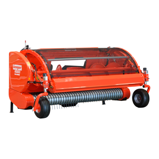
Page 9: Identification View
Identification View Identification View N3003 Pickup KM00321,0000A54 -19-21APR20-1/1 00-1 010421 PN=9... -
Page 10: Safety
Replacement safety signs are available from your KEMPER dealer. Before you start working with the machine, learn how to operate the machine and how to use controls properly. Do not let anyone operate without instruction. -
Page 11: Observe Road Traffic Regulations
Safety Observe Road Traffic Regulations Always observe local road traffic regulations when using public roads. FX,ROAD -19-01MAY91-1/1 Operator Ability and/or controls, and operating the machine properly and safely. • Machine owners must make sure that operators • Never allow a child or an untrained person to operate are responsible, trained, have read the operating the machine. -
Page 12: Prepare For Emergencies
Safety Prepare for Emergencies Be prepared if a fire starts. Keep a first aid kit and fire extinguisher handy. Keep emergency numbers for doctors, ambulance service, hospital, and fire department near your telephone. DX,FIRE2 -19-03MAR93-1/1 Wear Protective Clothing Wear close fitting clothing and safety equipment appropriate to the job. -
Page 13: Use Safety Lights And Devices
Safety Use Safety Lights and Devices Prevent collisions with other road users. Slow moving tractors with implements or drawn equipment, as well as self-propelled machines are especially dangerous on public roads. Always pay attention to traffic approaching from behind, particularly when changing direction. Provide for safe traffic conditions by using turn signals. -
Page 14: Practice Safe Maintenance
Safety Practice Safe Maintenance Understand service procedure before doing work. Keep area clean and dry. Never lubricate, service, or adjust machine while it is moving. Keep hands, feet, and clothing away from power-driven parts. Disengage all power and operate controls to relieve pressure. Lower equipment to the ground. -
Page 15: Service Tires Safely
Use power tools only to loosen threaded parts and fasteners. For loosening and tightening hardware, use the correct size tools. DO NOT use U.S. measurement tools on metric fasteners. Avoid bodily injury caused by slipping wrenches. Use only service parts meeting KEMPER specifications. KM00321,00008FF -19-02APR19-1/1 05-6 010421 PN=15... -
Page 16: Service Machines Safely
Safety Service Machines Safely Tie long hair behind your head. Do not wear a necktie, scarf, loose clothing, or necklace when you work near machine tools or moving parts. If these items were to get caught, severe injury could result. Remove rings and other jewelry to prevent electrical shorts and entanglement in moving parts. -
Page 17: Transport With Harvesting Unit Installed
Safety Transport with Harvesting Unit Installed Before driving forage harvester on public roads, raise harvesting unit and secure it in its fully raised position. It must not, however, obstruct operator's view of the road. In case of harvesting unit equipped with the crop deflector, always store the deflector in its transport position before driving on the road. -
Page 18: Avoid Heating Near Pressurized Fluid Lines
Dispose of Waste Properly If waste disposal is carried out improperly, this may damage the environment and ecological systems. Potentially harmful waste used with KEMPER equipment include such items as oil, fuel, coolant, brake fluid, filters, and batteries. Use leakproof containers when draining fluids. Do not use food or beverage containers that may mislead someone into drinking from them. -
Page 19: Decommissioning: Proper Recycling And Disposal Of Fluids And Components
• Contact your local environmental or recycling center, or or ordinances governing the handling or disposal of your KEMPER dealer for information on the proper way waste fluids (example: oil, fuel, coolant, brake fluid); to recycle or dispose of waste. -
Page 20: Safety Decals
Safety Decals Pictorial Safety Signs At several important places of this machine safety signs are affixed intended to signify potential danger. The hazard is identified by a pictorial in a warning triangle. An adjacent pictorial provides information how to avoid personal injury. -
Page 21: Repair And Maintenance
Safety Decals Repair and Maintenance Before carrying out adjustment, repair and maintenance work, shut off forage harvester engine and remove ignition key. KM00321,00009CC -19-16JAN20-1/1 Pickup DANGER - stay clear of header. Disengage header drive, shut off engine, and remove ignition key before servicing or unclogging header. -
Page 22: Hydraulic Lines
Safety Decals Hydraulic Lines Avoid the hazard by relieving pressure before disconnecting hydraulic or other lines. KM00321,00009CF -19-16JAN20-1/1 Stay clear of rotating driveshaft Entanglement in rotating driveshafts can cause serious injury or death. Keep driveshaft shields in place at all times. -
Page 23: Pressure Accumulator - Support Pressure Control Of The Windrow Compressor Roll
Safety Decals Pressure accumulator – Support pressure control of the windrow compressor roll Avoid bodily injuries from hydraulic oil and gas under pressure. KM00321,0000A56 -19-21APR20-1/1 Roller Compression Unit - Tips of Rake DANGER - Pay extreme attention when clearing blockages or working under a raised roller compression unit. -
Page 24: Haulage
Haulage Windrow Pickup Hanging Points Should the pickup be moved without attaching it to a self propelled forage harvester, use the hanging points shown. KM00321,0000268 -19-07FEB14-1/1 15-1 010421 PN=24... -
Page 25: Securing Pickup For Haulage (Lashing Points)
Haulage Securing Pickup for Haulage (Lashing Points) Lashing Points (Front) Lashing Points (Rear) A—Bracket During haulage on a truck or a trailer, use the intended NOTE: Remove brackets (A) from pickup after haulage. holes on the frame to secure the machine during haulage (see illustration). -
Page 26: Preparing The Pickup
Preparing the Pickup Unpacking and First Setup As soon as packaging material is removed, check the pickup for any damage that might have been incurred during transport. Complete pickup and assemble all options per instructions delivered with the pickup. KM00321,000010E -19-03FEB09-1/1 Set Gauge Wheel Height Adjust the pickup so that the cylinder teeth are X = 50 mm (2 in.) above the ground. -
Page 27: Check Adjustment Of Automatic Auger Lifting
Preparing the Pickup Check Adjustment of Automatic Auger Lifting After all options have been properly assembled, check adjustment of auger lifting device (A) on either side. For proper adjustment see Adjusting Automatic Auger Lifting in Operating the Pickup Section. A—Auger Lifting Device KM00321,0000A03 -19-11FEB20-1/1 25-2 010421... -
Page 28: Adjust Jackstand Height
Attaching the Pickup Adjust Jackstand Height When installing the pickup on a forage harvester for the first time, it is necessary to adjust the height of jackstands (A) in relation to the size of the tires on the harvester. To do this, it is necessary to take off the outer shields at left and right. - Page 29 Attaching the Pickup Attaching the Pickup IMPORTANT: Before attaching the pickup, refer to the Operator’s Manual of the forage harvester for the correct preparation or adaptation to the machine. NOTE: The pickup must be attached on level ground. Attach the pickup as follows: 1.
- Page 30 Attaching the Pickup 5. Close cam lock levers (A) on forage harvester and secure with quick-lock pin (B). IMPORTANT: Check that the locking pawl (C) is fully closed. A—Cam Lock Lever C—Locking Pawl B—Quick-Lock Pin Continued on next page KM00321,0000A61 -19-30APR20-3/7 30-3 010421 PN=30...
- Page 31 Attaching the Pickup 6. Secure pickup against falling of forage harvester: To prevent the pickup (A) from jumping out of the hitching rail (B) of the forage harvester, proceed as follows: • Loosen nut (B). • Turn plate (A) in the direction of the arrow until plate (A) rests under the locking pawl (C).
-
Page 32: Adjust The Scrapers
Attaching the Pickup 9. At left and right, raise jackstand (I) and secure with spring-loaded pin (A) in upmost position. A—Jackstand B—Pin KM00321,0000A61 -19-30APR20-6/7 10. Connect driveshaft (A) to the forage harvester. A—Driveshaft KM00321,0000A61 -19-30APR20-7/7 Adjust the Scrapers When installing the pickup on a forage harvester for the first time, the clearance between auger flights and scrapers must be adjusted. -
Page 33: Detaching The Pickup
Detaching the Pickup Detaching the Pickup IMPORTANT: Before detaching the pickup, make sure that pickup hydraulic functions are all depressurized. Follow the instructions below: 1. Lower the pickup to the ground. IMPORTANT: Leave the pickup standing at a height that allows the unit to be re-attached to the machine at a later time. - Page 34 Detaching the Pickup 6. Remove driveshaft (A). A—Driveshaft KM00321,0000A62 -19-24APR20-3/5 7. Open the cam lock lever (A) so that the locking pawl (B) is fully retracted. A—Cam Lock Lever B—Locking Pawl Continued on next page KM00321,0000A62 -19-24APR20-4/5 35-2 010421 PN=34...
- Page 35 Detaching the Pickup 8. Start the engine of the forage harvester. Lower the cutterhead assembly until the suspension rail (A) is a little below the frame tube (B) of the pickup. Move out of the pickup frame. A—Suspension rail B—Frame tube KM00321,0000A62 -19-24APR20-5/5 35-3 010421...
-
Page 36: Transporting
Transporting Observe Road Traffic Regulations machine of any potential danger and give him indications to maneuver and travel safely, especially when leaving the farm or the fields, CAUTION: Before transporting the machine and on roads at junctions. on public roads, make sure that the machine conforms to the regulations on the use of agricultural vehicles on the road. - Page 37 Transporting 4. Slowly lower the windrow compressor roll (A). IMPORTANT: Make sure that hydraulic pressure in the cylinders has been relieved fully. This ensures that the windrow compressor roll is lowered completely. A—Windrow Compressor Roll KM00321,0000A57 -19-22APR20-3/3 40-2 010421 PN=37...
-
Page 38: Operating The Pickup
Operating the Pickup Follow Safe Operating Procedures CAUTION: Before carrying out any adjustment always disengage all drives, shut off engine and wait until all moving parts have stopped. CAUTION: Before working on a raised pickup, place blocks underneath to prevent pickup from lowering. -
Page 39: Setting Windrow Compressor Roll In Operating Position
Operating the Pickup 3. Raise the windrow compressor roll (A) to its maximum height. CAUTION: Never work under a raised windrow compressor roll while the driver is still in the cab. A—Windrow Compressor Roll KM00321,0000A58 -19-30APR20-2/3 4. Close safety valve (A) to prevent windrow compressor roll from unintentional lowering. - Page 40 Operating the Pickup 2. Move the depth gauge wheels (A) outwards to their operating position. A—Depth Gauge Wheel KM00321,0000A59 -19-21APR20-2/3 3. Slowly lower the windrow compressor roll (A). NOTE: Depth gauge wheels are automatically unlocked and can turn freely when they are lowered onto the ground.
-
Page 41: Operating The Windrow Compressor Roll
Operating the Pickup Operating the Windrow Compressor Roll The contact pressure of the windrow compressor roll is adjusted by the oil pressure in the pressure accumulator (A). CAUTION: The pressure accumulator (A) may only be detached or put into operation by engineers or technicians trained in hydraulics. -
Page 42: Adjusting Roller Of Roller Compression Unit
Operating the Pickup Adjusting Working Height of Roller Compression Unit Add or remove shims (A) at rubber stop until there is a distance (X) of 3—5 mm (0.12—0.19 in.) between rake and feed auger wings. A—Shims X—3—5 mm (0.12—0.19 in.) KM00321,00009F9 -19-10FEB20-2/2 Adjusting Roller of Roller Compression Unit 1. -
Page 43: Roller Compression Unit Float Adjustment
Operating the Pickup Roller Compression Unit Float Adjustment When the roller compression unit is in operating position, adjust float mode as follows: 1. First adjust downstop (A) in the slot holes so that the stop (B) floats approximately 5 mm above the tube (C). 2. -
Page 44: Adjusting Gauge Wheel Height
Operating the Pickup Adjusting Gauge Wheel Height Adjust the pickup so that the cylinder teeth are 50 mm (2 in.) above the ground. To increase the clearance of the teeth from the ground, take out locking pin (A) and set gauge wheel (B) lower along the row of holes. -
Page 45: Adjusting Feed Auger Height
Operating the Pickup Adjusting Feed Auger Height Adjust feed auger springs. (See Adjusting Feed Auger Springs in this section.) When feed auger arm (E) rests on the rubber stop (D), the distance (G) between feed auger flight (A) and bottom sheet (F) should be within specification. -
Page 46: Adjusting The Scrapers
Operating the Pickup Adjusting the Scrapers 1. Slacken off nuts (A). 2. Move scrapers (B) forward to obtain specified clearance between flight (C) and the scrapers (B). Specification Flight to Scraper—Clearance..............0—2 mm (0—0.08 in.) 3. Retighten nuts (A). 4. Turn the auger by hand to make sure it can rotate freely. IMPORTANT: The scrapers must be installed with screw head facing down. -
Page 47: Adjusting Automatic Auger Lifting (Option)
Operating the Pickup Adjusting Automatic Auger Lifting (Option) When cylinders (A) are fully extended and the roller compression unit is completely raised, feed auger arm (B) must not touch the lower stop support (G). Adjust a minimum distance (X) of 1—3 mm (0.04—0.12 in.). If the distance is not correct, proceed as follows: 1. -
Page 48: Opening The Side Guard
Operating the Pickup Opening the Side Guard 1. Fold the gauge wheels inwards. 2. Open folding side guard (A) with a suitable tool, width across flats 13 mm. 3. Swing side guard (A) outwards. A—Side Guard KM00321,00009DD -19-22JAN20-1/1 Adjusting Feed Auger Paddles (Short Crops) The paddles (B) improve feeding in light and short crops. -
Page 49: Removing Feed Auger Paddles (High Crops)
Operating the Pickup Removing Feed Auger Paddles (High Crops) When harvesting high crops or winter forage crops, remove paddles (A) and paddle brackets (B) bolted on auger for smoother feeding. 1. Loosen bolts (C). 2. Remove paddle (A) and paddle bracket (B). Repeat procedure for each paddle. -
Page 50: Lubrication And Maintenance
Some lubricants may not be available in your location. Re-refined base stock products may be used if the finished lubricant meets the performance requirements. Consult your KEMPER dealer to obtain information and recommendations. Synthetic lubricants may be used if they meet the performance requirements as shown in this manual. -
Page 51: Lubricant Storage
KM00321,0000912 -19-11APR19-1/1 Mixing Lubricants In general, avoid mixing different brands or types of oil. Consult your KEMPER dealer to obtain information and Oil manufacturers blend additives in their oils to meet recommendations. certain specifications and performance requirements. -
Page 52: Every 10 Operating Hours - Pickup Driveshaft
Lubrication and Maintenance Every 10 operating hours — Pickup Driveshaft Lubricate with grease. KM00321,0000A5C -19-22APR20-1/1 Every 50 Hours — Pivoting Gauge Wheels Lubricate with grease. KM00321,00009FB -19-11FEB20-1/1 55-3 010421 PN=52... -
Page 53: Every 50 Hours - Lift Arms Of Roller Compression Unit
Lubrication and Maintenance Every 50 Hours — Lift Arms of Roller Compression Unit Lubricate with grease. KM00321,0000918 -19-11APR19-1/1 Every 50 Hours — Cylinder of Roller Compression Unit Lubricate with grease. KM00321,0000919 -19-11APR19-1/1 Every 50 Hours — Feeding Auger Pivot Points Lubricate grease. -
Page 54: Every 50 Hours - Jackstands
Lubrication and Maintenance Every 50 Hours — Jackstands Lubricate with grease. KM00321,000091B -19-11APR19-1/1 55-5 010421 PN=54... -
Page 55: Troubleshooting
Troubleshooting Pickup Operation before making any adjustments or performing any service operations. CAUTION: When lifting the pickup, place blocks underneath. Shut off the engine Symptom Problem Solution The pickup does not drop to the Front tires over-inflated Reduce tire pressure ground Float pressure too high Reset float pressure correctly... - Page 56 Troubleshooting Symptom Problem Solution Inside of scrapers is worn Spiral teeth on pickup collide with Find location of collisions, and rectify bent scrapers Increase pickup float Crop not conveyed, clogging at High-volume windrows and/or Reduce volume of windrows or slow feed opening excessive ground speed down...
-
Page 57: Service
Service Metric Bolt and Screw Torque Values TS1742 —UN—31MAY18 10.9 12.9 12.9 10.9 Class 4.8 Class 8.8 or 9.8 Class 10.9 Class 12.9 Bolt or Screw Hex Head Flange Hex Head Flange Hex Head Flange Hex Head Flange Size Head Head Head Head... -
Page 58: Adjust The Drive Chains
Service Adjust the Drive Chains Use idler sprocket (A) to tighten chain (B) which drives the conveyor auger. Adjust idler sprocket (A) to get a slack of 3 to 10 mm (0.12 to 0.4 in.) on the strand opposite the drive chain idler gear. Use idler sprocket (C) to tighten chain (D) which drives the pickup drum. -
Page 59: Trash Net
Service Trash Net Keep trash net (A) tensioned. If necessary, tighten screws (B) for proper tension. A—Trash Net B—Screws KM00321,000028F -19-31JAN14-1/1 Oil Reservoir of Central Chain Lubrication Fill oil reservoir of central chain lubrication with biodegradable oil (e.g. FUCHS PLANTOLUBE KS 46 N). IMPORTANT: Never use an oil that is not biodegradable. -
Page 60: Adjusting Oil Flow Of Central Chain Lubrication (Option)
Service Adjusting Oil Flow of Central Chain Lubrication (Option) Adjust oil flow at each chain as follows: 1. Remove cover (A). 2. Identify the screw allowing to adjust the oil flow of the relevant brush. 3. Turn the screw clockwise to increase oil flow and counterclockwise to decrease oil flow. -
Page 61: Storage
Storage Storing the Pickup Thoroughly clean pickup. Chaff and dirt will draw moisture Remove chains and wash them in solvent. Then dry them and cause rust. and coat them with heavy oil. Store pickup in a sheltered location, standing on its Touch up any worn or damaged paintwork. -
Page 62: Specifications
All missing or damaged safety-related components, including safety Periodically inspect and review the machine in conjunction signs, should be repaired or replaced before operating. with your KEMPER dealer. The review may result KM00321,000092C -19-13APR19-1/1 N3003 Pickup ...................... -
Page 63: Eu Declaration Of Conformity
Specifications EU Declaration of Conformity Kemper GmbH & Co.KG Am Breul D-48703 Stadtlohn, Germany The person named below declares that the product Machine type: Pickup Model: N3003 Fulfills all relevant provisions and essential requirements of the following directives: DIRECTIVE NUMBER... -
Page 64: Serial Number
4. When parking outdoors, store in a well-lighted and fenced area. 5. Make note of suspicious activity and report any thefts immediately to law enforcement agencies. 6. Notify your KEMPER dealer of any losses. KM00321,0000928 -19-12APR19-1/1 80-1 010421 PN=64... - Page 65 Index Page Page Lubricant Storage Storage, Lubricant........... 55-2 Adjusting Lubricants Automatic Auger Lifting (Option)......45-10 Mixing..............55-2 Feed auger height........... 45-8 Lubrication Feed Auger Paddles ..........45-11 Drive chains ............55-2 Feed Auger Springs ..........45-8 Feeding Auger Pivot Points ........55-4 Gauge Wheel Height..........
- Page 66 Index Page Page Serial number Transport Location ..............80-1 Road Traffic Regulations......... 40-1 Service Windrow Compressor Roll, Transport Position ..40-1 Adjusting the drive chains ........65-2 Trash Net..............65-3 Setting Windrow Compressor Roll in Troubleshooting Operating Position ............ 45-2 Pickup Operation ............
- Page 67 Index Index-3 010421 PN=3...
- Page 68 Index Index-4 010421 PN=4...
Need help?
Do you have a question about the Pickup N3003 and is the answer not in the manual?
Questions and answers