Table of Contents
Advertisement
Quick Links
Technology – you can depend on
Operators Manual
version B0507
English
No.93944
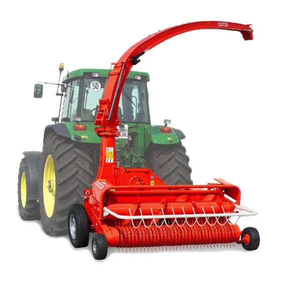
Champion C 3000
Tractor mounted -universal
Forage harvester
C3000
Maschinenfabrik KEMPER GmbH & Co. KG • D- 48694 Stadtlohn
Postfach 1352 • Telefon : +49 (0) 25 63 / 88-0
E-mail: Info@Kemper-Stadtlohn.de
Internet: www.kemper-stadtlohn.de
Advertisement
Table of Contents

Related Manuals for Kemper Champion C 3000


Summary of Contents for Kemper Champion C 3000
- Page 1 Operators Manual version B0507 English No.93944 Champion C 3000 Tractor mounted -universal Forage harvester C3000 Maschinenfabrik KEMPER GmbH & Co. KG • D- 48694 Stadtlohn Postfach 1352 • Telefon : +49 (0) 25 63 / 88-0 E-mail: Info@Kemper-Stadtlohn.de Internet: www.kemper-stadtlohn.de...
- Page 2 Table of contents C3000 Operating Instruction distribution B 0507 Nr. 90533 Chapter Operating instruction Range of use Accident prevention regulations Reference security 3.0 -4.0 Technical description Basic adjustments Mounting on tractor 3- Point hitch Hydraulic connection Electric connections Support wheels Horizontal attachment Rotating speed of the chute Transport positon chute...
- Page 5 Use of the machine in accordance with instructions also includes compliance with our Operating and maintenance conditions, as well as the exclusive use of original Kemper spare Parts. The Champion should only be used, serviced and repaired by those trained in operation of the machine and its inherent dangers.
- Page 10 You have made a good choice. We are pleased to congratulate you on Dear Customer your selection of a KEMPER machine. As your partner we offer quality and performance, together with reliable service. In order to be able to evaluate the conditions of use of our agricultural machines, and to take these requirements into consideration in the development of new units, we ask you to provide some information.
- Page 14 Overload safety clutches on the chopper. The Champion is equipped with 4 overload safety devices. 1. Ball clutch in the bevel gear drive of the gathering drums. 2 Slip clutch on the gathering drum PT0 3 Ball clutch on the top feed roll drive Ball clutch on the bottom feed roll drive Ball clutch in gathering drum gears.
- Page 15 Seperatly deliverd equipement C3000 Equipement depending order Separatly packed is the command terminal, the electric motor, screws, power cable lever to adjust fly wheel, operators manuel , parts catalog , PTO shaft and perforated plates. Equipement plates PTO shaft under 200 hp PTO shaft over 200 hp...
- Page 16 5.1 Basic adjustments C3000 Mounting on tractor Connect the 3-point hydraulic of the tractor with the chopper. Fix bottom attachment points against lateral movement. Choose tractor hydraulic on „ Position“ control Choose PTO 1000 U/pm 3-point hitch The 3 point hitch has two connec- tion facilities: in the middle of the machine or offset 150 mm on the side.
- Page 17 5.1 Basic adjustments C3000 Electric connections The header needs 12 V electricity Battery connect with red cable – Battery connect with blue cable Socket fix on rear ail Support wheels The height of the chopper can be adjusted by the support wheels. 1.
- Page 18 5.1 Basic adjustments C3000 Rotating speed of the chute The chute is rotated by a hydraulic motor. The speed of the chute motor can be set by 2 adjustable one-way restrictors. Transportpositon chute To respect the legal transport height of 4 m, use transport facility. Take off security blade and lift security lever.
- Page 19 5.1.1 Preparing to work C3000 Assemble chute Fix electric motor on chute of new chopper. Take of bolt release screw and put motor in position The cable is connected with motor by passing thru tube Make sure that chute can turn without crashing the cable.
- Page 20 5.1.1 Preparing to work C3000...
- Page 21 Basic adjustments C3000 Adapt PTO shaft Attention: ball clutch has always to be fixed on the chopper side! The length has to be adapted corresponding to the tractor. The minimum doubling of the shaft is 150mm The PTO shaft for tractors over 200hp cannot be adapted !! Tractors with more than 200 hp need special frame adapter The distance...
- Page 22 Basic adjustments C3000 To adapt PTO shaft, take off cardan protector Release small screw. Hold top and turn tube protector. Security will release. Pull back tube. The ball clutch is fixed on the chopper shaft with a 16X45 8.8 bolt. For security reasons the bolt is fitted with Loctite and torque.
- Page 23 Basic adjustments C3000 Push shaft up to the end . Clean PTO shaft. Fit screw from the inner side of the PTO shaft. Clean screw M 16X45 8.8 from grease and dirt. Put Loctite 234 on. Screw is fixed with a torque of 190 Nm.
- Page 24 5.3 Maize harvesting C3000 Connecting the header To connect the header take of spring adapter if working also with pick-up. Push connecting plate away. To avoid damages on cylinders lift them before connecting header. Move backwards and connect at first bottom fixing points.
- Page 25 5.3 Maize harvesting C3000 Attention: connect friction clutch on chopper gearbox Which shaft to choose look cutting length Important! Before first use of the machine make a service on friction clutch. Tighten bolts. Let chopper turn for 10 seconds. Discs will slip. Then release bolts up to top completely.
- Page 26 5.3 Maize harvesting C3000 Cutting length The cutting length gearbox has two possibilities to change gears. To pass lever into second position gearbox has to be in neutral position. Attention To pass between gears 1+2 to 3+4 gear levers have always to be in neutral position.
- Page 27 5.3 Maize harvesting C3000 Intake speeds & cutting length adjustment gathering drum Spur gear. With The speed of the feeding and intake these ratios in three gears, this gives devices is adjustable for each a total of 12 different speeds for the harvesting condition and crop type.
- Page 28 5.3 Maize harvesting C3000 Harvesting laid maize It is impossible to give specific rules as the conditions always vary so enormously but here is some general advice. - Drive at an angle to the laying direction as far as possible. . - For laid maize as per the sketch opposite, it is recommended that only rows should be harvested...
- Page 29 5.3 Maize harvesting C3000 Switch off rotating dividers The rotating dividers can be switched off. Lift lever an pull sideways to release v-belt Road protector In road position pull down protector In working position lift up an fold protector.
- Page 30 5.4 Modification for Grass Harvesting C3000 Mounting Pick-up with Metalldetector The Pick-up should only be mounted on choppers Grass harvesting contains a higher risk to pick up metall parts. Connect pick-up with bottom points and release stand. Release security and lift stand. Close at first bottom connection point.
- Page 31 5.4 Modification for Grass Harvesting C3000 Drop down chopper to get pick – up close. Connect spring and support Connect cylinder to lift pick-up and safe with lock pin. Connecting PTO shaft Push simple spider on gearbox shaft of pick-up. Attention: connect friction clutch on chopper gearbox Which shaft to choose look cutting...
- Page 32 5.4 Modification for Grass Harvesting C3000 Control and grease daily chain of pick-up. To control use special perforation. To tighten chains take off protector. Protector took off Release bolts of protector and use tighten bolts for higher tension After tightening lock security bolts and replace protector.
- Page 33 5.4 Modification for grass harvesting C3000 Take out 6 knives For grass harvesting it is necessary to take out 6 knives with knive holder. Release three bolts M 20X 45 8.8 Take out complete knive holder The interchangeable perforatetd plates have to be replaced by the smooth plates for grass.
- Page 34 5.4 Modification for grass harvesting C3000 Special checks before using for grass harvesting 1. Drive with a maximum of 6 blades only (as new a set as possible). See Table 26 2. Remove all other blades, blade holders and elevator paddles. 3.
- Page 35 5.5 Whole crop harvesting C3000 Operating instructions for whole crop silage such as standing dry crops, a good In view of the growing interest in this result can be achieved, but certain form of Silage, a kit has also been compromises are necessary for the developed for the Champion 3000 (for whole crop silage, winter barley,...
- Page 36 5.5 Whole crop harvesting C3000 Generel To obtain a proper cut, the rotation speed of the saws for thin-stemmed crops should be higher than for maize or sunflowers. In our experience, it is correct when the gathering drum speed is at least 28-36 rpm.
- Page 37 5.6 Sharpening Device C3000 To obtain an optimum chopping quality use the sharpening device several times a day. Working with the Sharpening Device Start chopper; PTO with 580 rpm; header is out of work! The disc must revolve when sharpening; eventually the revolutions of the tractor must be increased until sparks fly.
- Page 38 5.6 Sharpening Device C3000 Adjust chopping wheel! After sharpening the chopping wheel must be adjusted towards the counter blade. Even to compensate for wear check twice daily that the blades are parallel to the share bar. Open wheel protector. Release securing spring to release nut.
- Page 39 5.6 Sharpening Device C3000 Turn flywheel manualy until the blades touch the share bar. Then turn flywheel one spring turn back. The flywheel should not touch the share bar. Repeat adjustment. The gap between the blades and share bar should not exceed 0,5 The blades positionning is obtained by the long wholes.
- Page 40 5.6 Sharpening Device C3000 Change or turn shear bar! Control counter blades often.This saves fuel and ensures good chop quality See prcompression drums Ejector plates A high transportation performance of the chopped crops is depending on good ejectors. They can be turned four times.
- Page 41 5.7 Interchangable plates C3000 Depending of the harvesting crop the ground plate of the chopping wheel has to be changed. The Champion is designed with easily interchangeable: Smooth plate for grass Perforatetd cracing plate for maize By using a perforated plate the corn is better cracked. A more powerful tractor is needed.
- Page 42 5.7 Interchangable plates C3000 Improtant: Place center bolts into wholes in housing for correct working The side cracing plate can adjusted to different corn diameters The cracking plate works by means of an interchangeable perforated plate and varying the gap from the rocker paddles: The plate must fit flush at the bottom. The gap is 8 mm at section A-B, and 3 mm at section C-D.
- Page 43 5.7 Interchangable plates C3000 At the top the plate should be fitted as close as possible to the rocker paddles for ejection capacity. Adjustments: 1. Check weather the interchangeable plate covers the entire length 2 Check whether the contact points coincide 3 Adjust contact point II if necessary.
- Page 44 5.7 Interchangable plates C3000 Change of the bottom plate Lift chopper to change. The bottom plate ca be changed by releasing ten bolts. 10er release bolt Dobble use of plates The effective use of the cracking plates can be doubled by turning working direction.
- Page 45 5.8 Check and change shear bar C3000 and adjust smooth roller Check shear bar From the top of the fly wheel the shear bar can be checked visually To change shear bar lift up intake rollers. Therefore release one tour both sides the upper front bolts Take of bottom bolts on both sides.
- Page 46 5.8 Check and change shear bar C3000 and adjust smooth roller Lift up feed rollers with a long tube. The PTO shaft will open. For readjusting PTO shaft has to be put in together Before working put stand under lifted rollers.
- Page 47 5.8 Check and change shear bar C3000 and adjust smooth roller Change shear bar The shear bar can be checked, changed or turned Adjust scraper of smooth roller To adjust scraper release bolt M12. Adjust the scraper so that the gap between this and the smooth roller is no more than 0,5 mm and tighten screws firmly.
- Page 48 5.9 Metalldetector C3000 If the chopper is equipped with a metaldetector there are some hints: Electronical steering box bottom rubber feed drum ; clutch grips between drums and gearbox The sentivity of the metal detector can be adapted. Turn potentiometer in box.
- Page 49 5.9 Metalldetector C3000 The drive for the two front gathering drums, precompression and feed rollers is via the PTO, flywheel and gearbox. If foreign objects or clods cause, a blockage, the fuel flow to the intake System can .be cut off instantly (lever 10 at position "Autom.
- Page 50 5.9 Metalldetector C3000 1. The lifting spindle 1 is first connected to the cam plate 2 and set at an angle of 5° [position 0). In this position, the tension roller is in the middle of the cam plate. 2. The position switch 28A is then in the centre. 3.
- Page 51 5.10 Working with the chopper C3000 Working conditons of the header Connect header in base position so that PTO shaft is horizontal. Choose length of the top point so that chopper is vertical behind the tractor. To avoid damages on the chopper during the work adjust support wheel to obtain 5 cm between ground and the fly wheel housing.
- Page 52 5.10 Working with the chopper C3000 PTO revolutions Use PTO 1000 rpm To obtain an regular an good chopping quality keep PTO revolutions regular. Never use 4 th gear for security reasons and to protect gearbox. If you need different cutting length take out knives.
- Page 53 5.10 Working with the chopper C3000 Command terminal Chute position change Rücklauf R Revers.-Stop Autom. 0 Intake V Lamb on/off And touch button „ Revers – Stop“ =function activ only with metal detector. To release grip security „ Revers“ = gearbox moves backwards „...
- Page 56 1.Chute rotation point - 2 nipples 16 Roller chains - worm-gear and pick-up 2 Worm gear 17 Hinged points on holding down device 3 Front flywheel bearing 20 Spur gear Drums 4 Rear flywheel bearing 21 Transmission gear Drums 5 Torpedo dividers - Rotation point 22 Spur gear Precornpression roll 6 Hinged part of ejector double flap...
- Page 63 9.1 Circuit diagram C3000...
- Page 64 9.2 Circuit diagram - Remote control C3000...
Need help?
Do you have a question about the Champion C 3000 and is the answer not in the manual?
Questions and answers