
Subscribe to Our Youtube Channel
Related Manuals for Kemper 460 Plus


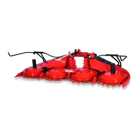
Summary of Contents for Kemper 460 Plus
- Page 1 Rotary Harvesting Unit OPERATOR'S MANUAL 460plus Rotary Harvesting Unit OMKM123547 ISSUE J0 (ENGLISH) Maschinenfabrik Kemper GmbH & Co. KG European Edition PRINTED IN U.S.A.
- Page 2 Use in any other way is considered as contrary to the other languages. To order, see your KEMPER dealer. intended use. The manufacturer accepts no liability for THIS MANUAL SHOULD BE CONSIDERED a permanent...
-
Page 3: Table Of Contents
497) ............25-11 Remove Paint Before Welding or Heating..05-8 Connecting the Drive (Types 496, 500) ....25-14 Avoid High-Pressure Jet on Safety Decals..05-8 Replace CLAAS Tray with KEMPER Tray..25-18 Dispose of Waste Properly .........05-8 Decommissioning: Proper Recycling Attaching to a FENDT Forage Harvester and Disposal of Fluids and Components ..05-9... - Page 4 Lubricant Storage ..........55-3 Rotary Harvesting Unit Method of Operation..40-1 At the Start of Every Harvesting Season ....55-3 Operating the Rotary Harvesting Unit - Use Genuine KEMPER Parts ......55-4 General Use ...........40-2 At the Start of Every Harvesting Clear Blockages ..........40-2 Season - Spherical Collar Bolts .....55-4...
- Page 5 Contents Page Storage Storage at End of Harvesting Season ....65-1 Start of New Season...........65-1 Specifications Machine Design Life ...........70-1 plus Rotary Harvesting Unit 460 ......70-1 Sound Level............70-1 EU Declaration of Conformity ......70-2 Serial Numbers Rotary Harvesting Unit Serial Number Plate ..75-1 Serial Number.............75-1 111320 PN=3...
- Page 6 Contents 111320 PN=4...
-
Page 7: Pre-Delivery Inspection
Pre-delivery Inspection Predelivery Checklist After the rotary harvesting unit has been completely □ Shipping brackets removed. assembled, inspect it to be sure it is in good running order before delivering it to the customer. Check off each item □ Rotary harvesting unit can be folded correctly. when found satisfactory or after making the necessary □... -
Page 8: After-Sale Checklist
Pre-delivery Inspection After-Sale Checklist The following items should be checked sometime during □ Check for worn rotary knives. the first season of operation with the rotary harvesting unit. □ Check with the customer as to the performance of the □ Go over the entire machine for loose or missing nuts rotary harvesting unit thus far. -
Page 9: Identification View
Identification View Identification View KM00321,00000C4 -19-14DEC11-1/1 00-1 111320 PN=9... -
Page 10: Safety
Replacement safety signs are available from your KEMPER dealer. Before you start working with the machine, learn how to operate the machine and how to use controls properly. Do not let anyone operate without instruction. -
Page 11: Observe Road Traffic Regulations
Safety Observe Road Traffic Regulations Always observe local road traffic regulations when using public roads. FX,ROAD -19-01MAY91-1/1 Operator Ability and/or controls, and operating the machine properly and safely. • Machine owners must make sure that operators • Never allow a child or an untrained person to operate are responsible, trained, have read the operating the machine. -
Page 12: Prepare For Emergencies
Safety Prepare for Emergencies Be prepared if a fire starts. Keep a first aid kit and fire extinguisher handy. Keep emergency numbers for doctors, ambulance service, hospital, and fire department near your telephone. DX,FIRE2 -19-03MAR93-1/1 Wear Protective Clothing Wear close fitting clothing and safety equipment appropriate to the job. -
Page 13: Stay Clear Of Harvesting Unit
Safety Stay Clear of Harvesting Unit Due to their function, the cutting rotors as well as gathering, cross and feed drums cannot be completely shielded. Stay clear of these moving elements during operation. Always disengage main clutch, shut off engine and remove key before servicing or unclogging harvesting unit. -
Page 14: Practice Safe Maintenance
Safety Practice Safe Maintenance Understand service procedure before doing work. Keep area clean and dry. Never lubricate, service, or adjust machine while it is moving. Keep hands, feet , and clothing from power-driven parts. Disengage all power and operate controls to relieve pressure. -
Page 15: Service Machines Safely
Safety Service Machines Safely Tie long hair behind your head. Do not wear a necktie, scarf, loose clothing, or necklace when you work near machine tools or moving parts. If these items were to get caught, severe injury could result. Remove rings and other jewelry to prevent electrical shorts and entanglement in moving parts. -
Page 16: Stay Clear Of The Intake Area
Safety Stay Clear of the Intake Area To avoid entanglement, do not feed crop into the machine by hand or foot. Do not attempt to clear obstructions while the machine is running. The feed rolls can feed crop material in faster than you can release your grip on the material. -
Page 17: Remove Paint Before Welding Or Heating
Dispose of Waste Properly If waste disposal is carried out improperly, this may damage the environment and ecological systems. Potentially harmful waste used with KEMPER equipment include such items as oil, fuel, coolant, brake fluid, filters, and batteries. Use leakproof containers when draining fluids. Do not use food or beverage containers that may mislead someone into drinking from them. -
Page 18: Decommissioning: Proper Recycling And Disposal Of Fluids And Components
• Contact your local environmental or recycling center, or fluids. Do not use food or beverage containers. your KEMPER dealer for information on the proper way • Do not pour waste fluids onto the ground, down a drain, to recycle or dispose of waste. -
Page 19: Safety Decals
Safety Decals Pictorial Safety Signs At several important places of this machine safety signs are affixed intended to signify potential danger. The hazard is identified by a pictorial in a warning triangle. An adjacent pictorial provides information how to avoid personal injury. -
Page 20: Service And Repair Work
Safety Decals Service and repair work Before carrying out repair and maintenance work, shut off engine and remove key. KM00321,0000A2B -19-20MAR20-1/1 Rotating Blades Do not touch any moving machine parts. Wait until moving parts have stopped. The rotating blades are not immediately stopped when the machine is shut down. -
Page 21: Folding Area Of The Rotary Harvesting Unit
Safety Decals Folding Area of the Rotary Harvesting Unit Stay clear of the folding area of the rotary harvesting unit. When folding or unfolding the rotary harvesting unit, ensure that no persons are present in the danger zone. Before folding or unfolding, ensure that all persons keep the required safety distance from the rotary harvesting unit. -
Page 22: Rotating Drums
Safety Decals Rotating Drums Stay clear of rotating drums. Risk of injury! Arms, legs or loose clothing might become caught by the rotating drums when in operation. Always keep the required safety distance from the rotating drums. Wait until moving parts have stopped. KM00321,0000A2F -19-20MAR20-1/1 Foldable Frame Never reach into the danger area while outer parts are still... -
Page 23: Haulage
Haulage Loading with a Crane Raise the rotary harvesting unit with a crossbar A—Chains B—Chains C—Crossbar The chains (A) and (B) must be pulled upwards vertically. CAUTION: When loading the rotary harvesting unit Therefore, use a traverse (C). with a crane, always use the suspension points. This prevents the machine from toppling over. - Page 24 Haulage Lifting the Rotary Harvesting Unit With Optional Lifting Eye Nut Kit CAUTION: When loading the rotary harvesting unit with a crane, always use the suspension points. This prevents the machine from toppling over. Make sure to use chains and hoisting devices that meet the weight requirements of the rotary harvesting unit (see "Specifications"...
-
Page 25: Secure The Rotary Harvesting Unit For Transport (Lashing Points)
Haulage Secure the Rotary Harvesting Unit for Transport (Lashing Points) Lashing points Lashing Points A—Bugee cords Continued on next page KM00321,000071E -19-10JAN18-1/2 15-3 111320 PN=25... - Page 26 Haulage Secure the rotary harvesting unit with bungee cords (A) on both sides as shown. Secure accessories with an additional bungee cord (optional). KM00321,000071E -19-10JAN18-2/2 15-4 111320 PN=26...
-
Page 27: Preparing The Rotary Harvesting Unit
Preparing the rotary harvesting unit Unpacking As soon as packaging material is removed, check the unit for any damage that might have been incurred during transport. OUKM001,0000027 -19-01MAR05-1/1 Adapt the Scrapers to the Feed Passage Before attaching the rotary harvesting unit to the forage harvester, ensure that the scrapers (A) match with the channel width of the forage harvester. -
Page 28: Attaching To A Claas Forage Harvester
Attaching to a CLAAS Forage Harvester Compatibility Chart The rotary harvesting unit is prepared for installation on the following CLAAS forage harvester types: CAUTION: Before attaching the rotary harvesting unit to a forage harvester, carry out the steps included in Section Preparing the Rotary Harvesting Unit. -
Page 29: Attaching To Type 498, 499 And 502 Forage Harvesters With Variable Header Drive
4. When entering a serial number, enter released by Claas. IMPORTANT: Enter a serial number of a rotary harvesting unit that corresponds to the working width of the Kemper rotary harvesting unit. Continued on next page KM00321,0000B1D -19-27OCT20-2/5 25-2 111320... - Page 30 Attaching to a CLAAS Forage Harvester IMPORTANT: The following entries must be released by Claas. 5. Use the old Orbis types when selecting the type of machine. NOTE: For example, in the case of an Orbis 900, select type 992 and not type I53 (see illustration). 6.
- Page 31 Attaching to a CLAAS Forage Harvester A—Adapter cable B—Main wiring harness connector IMPORTANT: Perform this step only for rotary 8. The adapter cable (A) must be removed from the harvesting units that have been equipped for Claas control unit (C) when the programming is attachment of a support wheel at the factory.
-
Page 32: Install Additional Wiring Harness (Only Forage Harvesters Of Types 498, 499 And 502)
Attaching to a CLAAS Forage Harvester Install additional wiring harness (only forage harvesters of types 498, 499 and 502) IMPORTANT: The additional wiring harness is supplied with the following rotary harvesting units and must be mounted on the forage harvester: •... - Page 33 Attaching to a CLAAS Forage Harvester 3. Install the socket outlet (A) on the Claas forage harvester with screws (B). NOTE: The mounting position of the socket outlet varies and depends on the manufacture year of the forage harvester. A—Socket outlet B—Bolts Mounting position of the socket outlet Mounting position of the socket outlet...
-
Page 34: Attaching To Claas Forage Harvesters
Attaching to a CLAAS Forage Harvester Attaching to CLAAS Forage Harvesters Rotary Harvesting Units with Standard Tilt Frame 1. Drive the forage harvester close to the rotary harvesting unit's frame until latching hooks (A) protrude into brackets (D) of the attaching frame. NOTE: Brackets (D) may be installed in two different positions. - Page 35 Attaching to a CLAAS Forage Harvester Rotary Harvesting Units with Attaching Frame for Support Wheel 1. Drive the forage harvester close to the rotary harvesting unit's frame until latching hooks (A) protrude into brackets (D) of the attaching frame. 2. Remove pins (C) on both sides. 3.
-
Page 36: Rotary Harvesting Units With Multi-Speed Gearbox And Quick Coupler
Attaching to a CLAAS Forage Harvester Rotary Harvesting Units with Multi-Speed Gearbox and Quick Coupler Adjust the quick coupler (only for initial use) 1. Make sure that attaching claw (A) on the rotary harvesting unit and attaching claw (B) on the forage harvester are in alignment. -
Page 37: Connect Hydraulic Hoses
Attaching to a CLAAS Forage Harvester Connect Hydraulic Hoses Connect hydraulic hoses (A) to forage harvester using quick couplers. A—Hydraulic hoses KM00321,0000179 -19-27MAY09-1/1 Connect the Drive (Type 492) NOTE: A step guard (A) for the u.j. shaft is installed on the input transmission. After the rotary harvesting unit has been attached to the forage harvester, the universal-jointed shaft for the drive must be installed. -
Page 38: Connecting The Drive (Types 493, 494 And 497)
Attaching to a CLAAS Forage Harvester Connecting the Drive (Types 493, 494 and 497) 1. Completely remove claw clutch (A) from rotary harvesting unit drive. To do this, disassemble items 1 to 11. A—Claw clutch KM00321,00008F4 -19-13MAR19-1/7 2. Screw threaded rod (B) into u.j. shaft, adjust to 147 mm (X) and counterlock with hex. - Page 39 Attaching to a CLAAS Forage Harvester 3. First insert universal-jointed shaft into splined bushing (A) of rotary harvesting unit drive on the forage harvester. A—Splined Bushing KM00321,00008F4 -19-13MAR19-3/7 4. Secure universal-jointed shaft with bushing (A) and retaining nut (B). A—Bushing B—Retaining Nut KM00321,00008F4 -19-13MAR19-4/7 5.
- Page 40 Attaching to a CLAAS Forage Harvester 6. Engage locking screw (A) into groove of splined shaft. Make sure that u.j. shaft can no longer move. Tighten lock nut (B). A—Locking Screw B—Lock Nut KM00321,00008F4 -19-13MAR19-6/7 7. Install universal-jointed shaft shaft shield (A) as shown. A—Universal-Jointed shaft F—...
-
Page 41: Connecting The Drive (Types 496, 500)
Attaching to a CLAAS Forage Harvester Connecting the Drive (Types 496, 500) 1. Completely remove claw clutch (A) from forage harvester header drive. To do this, remove plates (B), (C) and (D), and take off claw clutch (A). A—Claw clutch C—Metal Sheet B—Metal Sheet D—Metal Sheet... - Page 42 Attaching to a CLAAS Forage Harvester 3. Screw threaded rod (B) into u.j. shaft, adjust to 225 mm (8.86 in.) (X) and counterlock with hex. nut (A). A—Hex Nut X—225 mm (8.86 in.) B—Threaded Rod KM00321,0000B1F -19-27OCT20-3/8 4. Insert the universal-jointed shaft into header drive (A) on the forage harvester.
- Page 43 Attaching to a CLAAS Forage Harvester 7. Engage locking screw (A) into groove of splined shaft. Make sure that u.j. shaft can no longer move. Tighten lock nut (B). A—Locking Screw B—Lock Nut KM00321,0000B1F -19-27OCT20-5/8 8. Pre-assemble the bracket and install it on the header drive of the forage harvester.
- Page 44 Attaching to a CLAAS Forage Harvester NOTE: The u.j. shaft shield consists of 2 parts. 9. Install the universal-jointed shaft shield (A) on input transmission of the header drive and secure with screw (B). A—Universal-Jointed Shaft B—Screw Shield KM00321,0000B1F -19-27OCT20-7/8 10.
-
Page 45: Replace Claas Tray With Kemper Tray
This problem will be resolved by using the straight KEMPER tray (A). Installation: Remove CLAAS tray, slide in straight KEMPER tray (A) and attach it to support shaft (B). NOTE: When harvesting grass, remove the KEMPER tray. -
Page 46: Attaching To A Fendt Forage Harvester
Attaching to a FENDT Forage Harvester Align the Oscillating Frame Align oscillating frame (A) with linear module (B). A—Oscillating Frame B—Linear Module KM00321,0000126 -19-23MAR12-1/1 Attach the Rotary Harvesting Unit to FENDT Forage Harvesters 1. Use tensioning lever (A) to open the lock. A—Tensioning Lever KM00321,0000184 -19-12JUN12-1/5 2. - Page 47 Attaching to a FENDT Forage Harvester 3. Raise the lifting gear until pins (B) engage in the lower latches (A) at left and right. 4. Stop the engine. 5. Apply the park brake. A—Latches B—Pin KM00321,0000184 -19-12JUN12-3/5 6. Use tensioning lever (A) to close the lock. A—Tensioning Lever KM00321,0000184 -19-12JUN12-4/5 7.
-
Page 48: Connect Hydraulic Hoses And Wiring Harness
Attaching to a FENDT Forage Harvester Connect Hydraulic Hoses and Wiring Harness The hydraulic outlets on the forage harvester are numbered. Connect the numbered hydraulic hoses of the rotary harvesting unit to the relevant hydraulic outlets of the forage harvester. Connect wiring harness (A) to the electrical socket on the forage harvester. -
Page 49: Change The Hydraulic System
Attaching to a FENDT Forage Harvester 2. Slide the guard over the joint until it engages. KM00321,00001DE -19-07MAY13-2/3 3. Press sliding pin (A) and slide the joint onto the splined shaft on the forage harvester until sliding pin (A) engages in the ring-shaped groove. A—Sliding Pin KM00321,00001DE -19-07MAY13-3/3 Change the Hydraulic System... -
Page 50: Unlock The Oscillating Frame
Attaching to a FENDT Forage Harvester Ball cock positions 1— Position for Maize 2— Position for Grass KM00321,000012D -19-29MAR12-2/2 Unlock the Oscillating Frame Remove locking pin (A) and insert it in hole (B) in the oscillating frame. NOTE: The oscillating frame is now unlocked. A—Locking Pin B—Hole KM00321,000012F -19-29MAR12-1/1... -
Page 51: Detaching The Rotary Harvesting Unit
Detaching the Rotary Harvesting Unit Detach the Rotary Harvesting Unit NOTE: Fold the rotary harvesting unit before setting it down. 1. Lower the rotary harvesting unit to the ground. 2. Shut off the forage harvester's engine, remove the key from the ignition and apply the parking brake. 3. -
Page 52: Transport
Transport Driving on Public Roads regulations when driving the forage harvester on public roads. CAUTION: When driving on public roads or Fold the outer sections for transport according to the local highways at night or during the day, observe local regulations. -
Page 53: Driving On Public Roads (Rotary Harvesting Units With Comfort Support Wheel)
Transport Driving on Public Roads (Rotary Harvesting Units with Comfort Support Wheel) A—Protective curtains B—Position Lamps/Turning C—Support wheel Lights IMPORTANT: Rotary harvesting units equipped for Position Lamps and Turning Lights: installation of the comfort support wheel (C) may be driven on public roads only if the As the position lamps and turning lights on the forage comfort support wheel is actually attached. -
Page 54: Driving On Public Roads (Rotary Harvesting Units Without Comfort Support Wheel)
Transport Driving on Public Roads (Rotary Harvesting Units without Comfort Support Wheel) When driving on public roads, the entire area around the crop separators must be covered with a protective guard (A). Protective guard (A) assembly sequence: 1. Wait until rotating blades have come to a complete stop. -
Page 55: Operating The Rotary Harvesting Unit
Operating the Rotary Harvesting Unit Rotary Harvesting Unit Method of Operation A—Gathering Drum D—Lengthwise Direction of Crop F— Feed Teeth H—Feed Bar B—Dividers E—Feed Drum G—Guides and Scrapers C—Rotating Blade The rotary harvesting unit can approach the crop in (F) and so the stalks are conveyed along the guides and different ways - it can operate along the rows, across the scrapers (G) to the feed drums (E). -
Page 56: Operating The Rotary Harvesting Unit - General Use
Operating the Rotary Harvesting Unit Operating the Rotary Harvesting Unit - Operating the Rotary Harvesting Unit General Use Once the cutterhead is turning at the correct speed, and Starting the Forage Harvester the rotary cutters are at the appropriate speed, drive into the standing crop. -
Page 57: Adjust Skid Shoes Parallel To The Ground
Operating the Rotary Harvesting Unit Adjust Skid Shoes Parallel to the Ground As soon as rotary harvesting unit has reached its operating position: Make sure that skid shoes (A) are parallel to the ground. Depending on the angle of the rotary harvesting unit to the ground, it may be necessary to remove spacers (B). -
Page 58: Adjusting The Central Feed Bar
Operating the Rotary Harvesting Unit Adjusting the Central Feed Bar NOTE: If the crop is short, set the central feed bar (A) low. Feed bars (A) and (B) guide the cut crop inwards and ensure better feeding. The height of the central feed bar (C) can be altered in the field to suit the current crop conditions. -
Page 59: Gathering Drum Operating Speeds
2 speeds. See forage harvester Operator's Manual for adjustments to the forage harvester. On the KEMPER rotary harvesting unit, 1st gear (A) and 2nd gear (B) are shifted directly at the drive case. A—1. Gear B—2. Gear... -
Page 60: Length Of Cut And Drum Speeds With Claas Forage Harvester 830-900 (Types 492, 496, And 500)
Operating the Rotary Harvesting Unit Length of Cut and Drum Speeds with CLAAS Forage Harvester 830-900 (Types 492, 496, and 500) See tables below to determine length-of-cut adjustment. KM00321,0000B23 -19-29OCT20-1/1 Cutterhead with 24 Knives (Types 492, 496, and 500) I—Length of cut, II—Lever (B) position III—Lever (A) IV—Lever (C) -
Page 61: Length Of Cut And Drum Speeds With Claas Forage Harvester 830-900 (Type 493)
Operating the Rotary Harvesting Unit Length of Cut and Drum Speeds with CLAAS Forage Harvester 830-900 (Type 493) 2-Speed Gear Box The two-speed gear box of the rotary harvesting unit is available in two versions: • Speed increase for normal to long length of cut (standard) •... - Page 62 Operating the Rotary Harvesting Unit Two-speed gear box (III) for short length of cut (option) I—Length of cut, number of knives II—Length-of-cut III—Rotary harvesting IV—Gathering drum transmission, forage unit drive speed harvester 2x14 knives 2x7 knives Gear Gear 3.4 mm (0.13 in.) 6.8 mm (0.27 in.) 4.3 mm (0.17 in.) 8.6 mm (0.34 in.)
-
Page 63: Cutterhead With 24 Knives (Type 493)
Operating the Rotary Harvesting Unit Cutterhead with 24 Knives (Type 493) Two-speed gear box (III) for normal to long length of cut (standard) III—Rotary harvesting I—Length of cut, number of knives II—Length-of-cut IV—Gathering drum transmission, forage unit drive speed harvester 2x12 knives 2x6 knives Gear... - Page 64 Operating the Rotary Harvesting Unit Two-speed gear box (III) for short length of cut (option) I—Length of cut, number of knives II—Length-of-cut III—Rotary harvesting IV—Gathering drum transmission, forage unit drive speed harvester 2x12 knives 2x6 knives Gear Gear 4 mm (0.16 in.) 8 mm (0.31 in.) 5 mm (0.20 in.) 10 mm (0.39 in.)
-
Page 65: Cutterhead With 20 Knives (Type 493)
Operating the Rotary Harvesting Unit Cutterhead with 20 Knives (Type 493) Two-speed gear box (III) for normal to long length of cut (standard) III—Rotary harvesting I—Length of cut, number of knives II—Length-of-cut IV—Gathering drum transmission, forage unit drive speed harvester 2x10 knives 2x5 knives Gear... -
Page 66: Length Of Cut And Drum Speeds With Claas Forage Harvester 930-980 (Types 494, 497, And 498)
Operating the Rotary Harvesting Unit Two-speed gear box (III) for short length of cut (option) I—Length of cut, number of knives II—Length-of-cut III—Rotary harvesting IV—Gathering drum transmission, forage unit drive speed harvester 2x10 knives 2x5 knives Gear Gear 5.0 mm (0.20 in.) 10.0 mm (0.39 in.) 6.2 mm (0.24 in.) 12.3 mm (0.48 in.) -
Page 67: Cutterhead With 36 Knives (Types 494, 497, And 498)
Operating the Rotary Harvesting Unit Cutterhead with 36 Knives (Types 494, 497, and 498) Two-speed gearbox (II) for normal to long length of cut (standard) II—Rotary harvesting unit drive I—Length of cut, number of knives III—Gathering drum speed 2x18 knives 2x9 knives Speed 4 mm (0.16 in.) -
Page 68: Cutterhead With 24 Knives (Types 494, 497, And 498)
Operating the Rotary Harvesting Unit Cutterhead with 24 Knives (Types 494, 497, and 498) Two-speed gearbox (II) for normal to long length of cut (standard) II—Rotary harvesting unit drive I—Length of cut, number of knives III—Gathering drum speed 2x12 knives 2x6 knives Speed 6 mm (0.24 in.) -
Page 69: Adjusting Gear Selection With Multi-Speed Gearbox For Claas Forage Harvesters
Operating the Rotary Harvesting Unit Adjusting Gear Selection with Multi-Speed Gearbox for CLAAS Forage Harvesters The multi-speed drive for CLAAS forage harvesters has 4 speeds. The first 2 speeds are selected by turning nut (B) on the outside of the drive. The entire multi-speed drive can be rotated so that 2 more speeds (A) can be selected. -
Page 70: Lengths Of Cut And Gear Selection With Multi-Speed Gearbox For Claas Forage Harvesters
Operating the Rotary Harvesting Unit 3. Rotate drive (C) through 180°. NOTE: The gearbox can be rotated without taking it off. 4. Tighten hex socket screws (D) to specification. Specification Gearbox, Hex Socket Screws—Torque............95 N·m (70 lb.-ft.) 5. Re-install universal-jointed shaft (E) and shield (F). C—Gearbox E—Universal-Jointed Shaft D—Hex Socket Screws... -
Page 71: Harvest
Operating the Rotary Harvesting Unit Harvest Before the harvest, do the following: - Unfold the rotary harvesting unit - Adjust the feed bars - Adjust the speed at which the gathering drums operate IMPORTANT: Avoid unnecessary wear at the clutches. From the idle setting, always select forward gear. -
Page 72: Additional Equipment
Additional Equipment Special Kit for Row Guidance (Steering • (1) sensor system with connecting cables Assistance) • (1) set of hardware for installation on rotary harvesting unit When driving a forage harvester 90% of the driver's • (1) assembly instructions attention is focused on steering. -
Page 73: Troubleshooting
Poor cut when the rows are far The machine is tackling 5 rows of Tackle only 4 rows of plants. Contact apart. plants. The middle row is hindering your KEMPER dealer if necessary. the cut. KM00321,00000D6 -19-22DEC11-1/1 50-1 111320 PN=73... -
Page 74: Lubrication And Periodic Service
Lubrication and Periodic Service Service Intervals IMPORTANT: Replace any damaged parts. Any screws that have worked loose must be CAUTION: Before making any adjustments or retightened to the proper torque. doing any service work, always: - Switch the machine off Clean grease fittings before lubrication. -
Page 75: Transmission Oil
A 50% mixture of ethylene coolant in water provides coolant. freeze protection to -37°C (-34°F). If protection at lower temperatures is required, consult your KEMPER dealer for recommendations. KM00321,0000196 -19-10JUN09-1/1 55-2... -
Page 76: Alternative And Synthetic Lubricants
The temperature limits and service intervals shown in Some lubricants may not be available in your location. this manual apply to both conventional and synthetic Consult your KEMPER dealer to obtain information and lubricants. recommendations. Re-refined base stock products may be used if the finished lubricant meets the performance requirements. -
Page 77: Use Genuine Kemper Parts
KEMPER. Installation and use of such products could have negative effects upon the design characteristics of KEMPER machines and thereby affect their safety. Avoid this risk by using only genuine KEMPER parts. KM00321,00002CD -19-03MAY10-1/1 At the Start of Every Harvesting Season -... -
Page 78: At The Start Of Every Harvesting Season-Gearbox Mounting Flange Attaching Screws
Lubrication and Periodic Service At the Start of Every Harvesting Season—Gearbox Mounting Flange Attaching Screws The torques of the flange screws (A) at gearbox mounting flanges of gathering drums must be retighten prior to each harvesting season and then retighten after 50 hours in service. -
Page 79: At The Beginning Of Each Harvesting Season - Adjust Latch Of The Chassis (Optional)
Lubrication and Periodic Service At the beginning of each harvesting season — adjust latch of the chassis (optional) Rotary harvesting units for Claas forage harvesters Rotary harvesting units for Fendt forage harvesters A—Shaft X—Setting Dimension B—Dog Insert a 35 mm (1.38 in.) diameter shaft (A) into jaw (B). Adjust dimension (X) of brace so that shaft (A) fits in dog Close Jaw (B) by folding the rotary harvesting unit up. -
Page 80: General View Of Drives And Oil Levels In The Rotary Harvesting Unit
Lubrication and Periodic Service General view of drives and oil levels in the rotary harvesting unit A—Oil drain screw 2— Bevel gear drive - 1.5 L (0.4 4— Spur-gear angle drive - 1.1 L B—Oil filler plug US. gal.) (0.29 US. gal.) C—Vent 3—... -
Page 81: Overview Of Oil Levels In Input Transmission
Lubrication and Periodic Service Overview of oil levels in input transmission Rotary harvesting units for CLAAS forage harvesters A—Gear box - 4.3 L (1.14 U.S. C—4-Speed Multi-Speed Drive gal.) (Option) - 1.25 L (0.33 U.S. B—Bevel gear drive for gal.) quick-coupler (option) - 1.2 L (0.32 U.S. -
Page 82: Every 10 Hours Of Operation-Cleaners And Blade Rotor Segments
Lubrication and Periodic Service Rotary harvesting units for FENDT forage harvesters (types T658 and T659) NOTE: See the forage harvester type plate for the exact type designation. A—Bevel gear drive - 2,0 L (0.53 U.S. gal.) KM00321,0000B28 -19-29OCT20-3/3 Every 10 Hours of Operation—Cleaners and Blade Rotor Segments Check all cleaners (A) and blade rotor segments (B) for signs of wear. -
Page 83: Every 10 Operating Hours-Balance Weights
Lubrication and Periodic Service Every 10 Operating Hours—Balance Weights Check balance weights (A) beneath the outer blade rotors for wear. Replace any damaged or worn balance weights and screws. Install screws with Loctite® 270 and tighten to the specified torque. Specification Balance weight mounting screws—Torque ............ -
Page 84: Every 50 Hours-Claw Clutch
Lubrication and Periodic Service Every 50 Hours—Claw Clutch Clean all the claw clutches (see arrows). Lubricate with grease. Apply also a layer of grease to the grooved surface of the clutch claws using a brush. KM00321,00001B8 -19-17JUN09-1/1 Every 50 Hours—Lower Pin of Hydraulic Cylinder and Hinges of the Outer Units Lubricate with grease. -
Page 85: Every 50 Hours-Upper Rolls Of Oscillating Frame
The cavity of the friction clutch (A) can be drained and refilled. This service work requires the friction clutch to be removed from the machine. Therefore it is advised to contact your KEMPER dealer to drain/refill the friction clutch. Specification Main drive friction clutch cavity—Capacity ............ -
Page 86: After Each Harvesting Season
After Each Harvesting Season • Clean the entire rotary harvesting unit - pay particular from your KEMPER dealer, so that they can be installed attention to the depressions (A) in the gathering drums. in time for the next harvesting season. -
Page 87: Service
Service Metric Bolt and Screw Torque Values TS1670 —UN—01MAY03 10.9 12.9 12.9 12.9 12.9 10.9 Class 4.8 Class 8.8 or 9.8 Class 10.9 Class 12.9 Bolt or Screw Size Lubricated Lubricated Lubricated Lubricated lb.- lb.- lb.- lb.- lb.- lb.- lb.- lb.- 11.3 16.5... -
Page 88: Relieve Pressure On The Main Drive Slip Clutches
4. Loosen screws (C) as far as the threads allow (without removing them completely). 5. Position cover (A) and install using screws (B). IMPORTANT: It is recommended to have the slip clutches checked once a year by the KEMPER dealer. KM00321,000019C -19-12JUN09-2/2 60-2 111320 PN=88... -
Page 89: Disassemble Slip Clutch
Service Disassemble Slip Clutch If it is not possible to turn slip clutch by hand as explained under ”Relieving Pressure at the Slip Clutches on the Main Drive”, it has to be disassembled and cleaned for proper function. Proceed as follows: 1. -
Page 90: Installing New Rotating Blades
Service Installing New Rotating Blades A—Yellow Blade C—Strap E—Cleaner (Clockwise) B—Black Blade D—Cleaner (Counterclockwise) F— Reinforcement Strap 2. The blades are installed in the following order: 2 CAUTION: Before carrying out adjustment yellow (A), then 2 black (B). Remember to tighten the or service work, ALWAYS: straps (C). -
Page 91: Adjusting The Dividers
Service NOTE: Install cleaners (D) and (E) with their cutting edges pointing in the direction of cut. KM00321,00000DA -19-22DEC11-2/3 Tighten all attaching screws of blade segments and cleaners with the specified torque. Specification Screws (M8)—Torque ..............28 Nm 20.65 lb-ft Screws (M10)—Torque ..............51 Nm 37.62 lb-ft A—Screws (M8) B—Screws (M10) -
Page 92: Checking Scrapers Adjustment
Service Checking Scrapers Adjustment In order to prevent plugging in the feeding channel, the scrapers (A) have to be set as close as possible to the gathering drums. The scrapers might touch the drums slightly. The scraper (A) can be adjusted thanks to slot holes (B). A—Scraper B—Slot hole OUCC002,0002834 -19-15OCT07-1/1... -
Page 93: Cleaning Rotary Harvesting Unit
Service Check condition of the cleaners (C) frequently. Replace worn parts. C—Cleaners KM00321,0000150 -19-27MAR09-2/2 Cleaning Rotary Harvesting Unit Remove loose crop by means of compressed air and/or a hand brush. When using high pressure/steam cleaners, keep a minimum distance (X) of 250 mm (9.84 in.). Refer to specifications for the maximum temperature and maximum pressure. -
Page 94: Storage
• Check the rotary harvesting unit for damaged or worn parts and replace them as necessary. For more detailed checks, see your KEMPER dealer. • Touch up the paintwork if required, and clean the decals. KM00321,000019E -19-12JUN09-1/1 Start of New Season •... -
Page 95: Specifications
All missing or damaged safety-related components, including safety Periodically inspect and review the machine in conjunction signs, should be repaired or replaced before operating. with your KEMPER dealer. The review may result KM00321,00004C9 -19-30NOV15-1/1 plus Rotary Harvesting Unit 460 .......................... -
Page 96: Eu Declaration Of Conformity
Specifications EU Declaration of Conformity Kemper GmbH & Co.KG Am Breul D-48703 Stadtlohn, Germany The person named below declares that the product Machine type: Rotary harvesting unit plus Model: 460 fulfills all relevant provisions and essential requirements of the following directives:... -
Page 97: Serial Numbers
Serial Numbers Rotary Harvesting Unit Serial Number Plate A—Type D—Weight B—Model Designation E—Year of Construction C—Product Identification F— Model Year Number KM00321,00000DF -19-22DEC11-1/1 Serial Number When ordering parts, always quote the rotary harvesting unit serial number. The serial number is on a plate located on the right side of the frame. - Page 98 Serial Numbers 75-2 111320 PN=98...
- Page 99 Index Page Page Adjust scrapers............20-1 Alternative lubricants ..........55-3 End of season Attach Storage ..............65-1 Attaching to CLAAS forage harvesters Connecting the Drive (Types 493, 494 and 497) ............25-11 Attaching Feed Bar Attaching to CLAAS Forage Harvesters ....25-7 Adjustment ..............
- Page 100 Index Page Page Length of Cut and Drum Speeds Rotary Harvesting Unit Method of Operation CLAAS Forage Harvesters Dividers ..............40-1 Type 493.............. 40-7 Feed Bar ..............40-1 Length-of-cut adjustment Feed Drum .............. 40-1 CLAAS forage harvester ......... 40-5 Feed Teeth .............. 40-1 Loading with a Crane..........
- Page 101 Index Index-3 111320 PN=3...
- Page 102 Index Index-4 111320 PN=4...
Need help?
Do you have a question about the 460 Plus and is the answer not in the manual?
Questions and answers