Table of Contents
Advertisement
Quick Links
Harvesting maize with perfect technology
Operating Manual
Issue B0509
English
No. 93 940
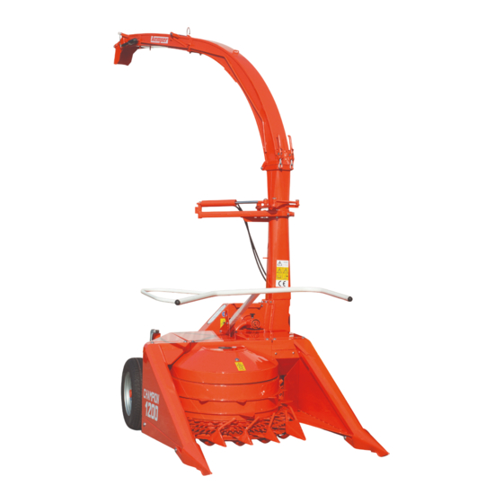
Champion C 1200
MOUNTED UNIVERSAL
FORAGE HARVESTER
Maschinenfabrik KEMPER GmbH & Co. KG D-48694 Stadtlohn, Germany
Postfach 1352 Telephone: +49 (0) 2563 /88-0
E-mail: Info@Kemper-Stadtlohn.de
Internet: www.kemper-stadtlohn.de
Advertisement
Table of Contents

Related Manuals for Kemper Champion C 1200


Summary of Contents for Kemper Champion C 1200
- Page 1 Harvesting maize with perfect technology Operating Manual Issue B0509 English No. 93 940 Champion C 1200 MOUNTED UNIVERSAL FORAGE HARVESTER Maschinenfabrik KEMPER GmbH & Co. KG D-48694 Stadtlohn, Germany Postfach 1352 Telephone: +49 (0) 2563 /88-0 E-mail: Info@Kemper-Stadtlohn.de Internet: www.kemper-stadtlohn.de...
- Page 2 Claims arising from Kempers policy is one of contineous development and improvement and we therefore design reserve the right to alter design and specifications without notice. Telephone National Sales Management +49 (0) 25 63 - 88 33 Sales, Machinery +49 (0) 25 63 - 88 34 Shipping Status +49 (0) 25 63 - 88 35 Sales, Spare Parts...
- Page 3 Table of contents C1200 Operating Manual Issue B0509 English No. 81640 Chapter Safety instructions Product liability Introduction – Scope of application Standard model Special equipment Technical data 12.0 Champion harvesting technology 19.0 Technical instructions 22.0 Installation of ejection chute 23.0 Basic settings of mounted forage harvester 24.0 Attachment options...
- Page 4 24. The hydraulic system is under high pressure. All damages or deteriorated hoses have to be replaced immediately. In any case the hoses and hydraulic lines have to be replaces every six years. 25. Do not exceed the permissible hydraulic pressure of 210 bar. 26. Use only genuine KEMPER spare parts.
- Page 5 1 Safety instructions C 1200 Shut off engine and remove key before Carefully read the Operator’ s Manual performing maintenance or repair work before handling the machine. Hydraulik Druck max. Hydraulic pressure of Pression Hydraulique de 1000 Hydraulische Druck max. 2 1 0 bar...
- Page 6 1 Safety instructions C 1200 Danger by turning cutting rotor. Keep Keep hands away from rotating crop distance. dividers. Put safety shields in place when grinding Wait until all machine components have knives. Wear safety glasses. completely stopped before touching them.
- Page 7 1 Safety instructions C 1200 Stay clear of rotating drive line to avoid Avoid fluid escape under pressure. personal injury. Read the users manual. Change hoses immediately. A Adjust the flywheel only with safety gloves B Grind the knives with safety glasses C Close grinder sheet immediately after the flywheel has stopped turning...
- Page 8 You have made a good choice. We are pleased to congratulate you on you Dear customer selection of a KEMPER machine. As your partner we offer quality and perfor- mance, together with reliable service. In order to be able to evaluate the conditions of use of our agricultural machi- nes, and to take these requirements into consideration in the development of new units, we ask you to provide some information.
- Page 9 Otherwise no warranty will be assumed for resulting damage. Observation of the operation maintenance instructions specified by the manufacturer and exclusive use of genuine KEMPER spare parts shall also be taken to be a part of operation in accordance to specifications.
- Page 10 7 Standard Equipment C 1200 Mounting facility The special drive system allows three mounting options with the same basic machine: FRONT MOUNTING – REAR MOUNTING – SIDE MOUNTING The machine can be hitched to any tractor with cat. II 3-pt hydraulics. Power transmission Main PTO drive shaft with friction clutch and freewheel mechanism.
- Page 11 8 Optional Equipment C 1200 Cutting lengths V-belt pulley W Cutting knives 1 = 153 mm 65975 1= 218 mm 65977...
- Page 12 5 – 7.5 – 10 – 15 – 20 – 30 Mounting facility The CHAMPION C 1200 can be operated by conventional tractors and by system tractors as well. Hitch options are the combined REAR and SIDE MOUNTING and FRONT MOUNTING. The new drive system allows any of these three options to be used by swinging the divided transmission system into the desired position.
- Page 13 10 Designation of assembly groups C 1200...
- Page 14 10 Designation of assembly groups C 1200 1. Two-piece discharge flap 2. 12 V electromotor for two-piece flap 3. Foldable discharge chute 4. Hydr. turntable (140°) chute 5. Hydr. connection for double spool valve 6. 12 Volt plug 7. Readjustable disc wheel 1180 rpm 12 chopping knives with wolfram layer 8.
- Page 15 12 Champion harvesting technology C 1200...
- Page 16 12 Champion harvesting technology C 1200 Champion chopping technique Principle functions of the Champion (Fig. 19) The patented cutting system of the Champion allows the stalks of the crops to be cut in any direction – in a lengthwise, transverse or oblique sense to the rows. None of the stalks can escape the area of the rotary cutter.
- Page 17 19 Technical instructions C 1200...
- Page 18 19 Technical instructions C 1200 Steering capability Sufficient steering capability is only ensured if at least 20 % of the total weights are acting onto the tractor front axle. Hitch The hitch is not designed for supporting any additional load. Please also observe the corresponding decal placed on the machine.
- Page 19 19 Technical instructions C 1200...
- Page 20 19 Technical instructions C 1200 Overload clutch of the Another overload clutch is fitted to the feed drum. This clutch is only feed drum operative with the power band set to the correct tension when spring 12 (Fig. 30 A) is so adjusted that the measurement 270 mm is given.
- Page 21 22 Ejection chute C1200 Installation of ejection chute after delivery After delivery of the machine, mount the servomotor of the ejection flap. Remove the split cutter pin from the securing bolt and mount the motor. Feed the cable of the servomotor through the cable duct.
- Page 22 24 Attachment options C1200 Three attachment options Front-mounted Rear-mounted Side-mounted The Champion C1200 can be operated in three different positions to the tractor. In order to mount the header to the front of the tractor, turn the input bevel gear transmission (see instructions).
- Page 23 24 Attachment options C1200 Conversion for front mounting Swivelling bevel gear transmission To adjust the machine for front mounting, turn the bevel gear transmission. To do this, you must dismantle both drive shafts. Remove the M8 screws from the shaft safety guard.
- Page 24 24 Attachment options C1200 Turning of header Turning header to change from rear to side attachment Securing key The header is kept in its position by means of a keyed joint. To swivel the Stop header to change its mounting position or for maintenance work, remove the key.
- Page 25 25 Working with the forage harvester C1200 Alignment of forage harvester The mounted forage harvester should be attached in such a way that the drive shaft is straight when the machines are in working position. To achieve this, align the forage harvester by means of the upper link so that it is perpendicular to the floor.
- Page 26 25 Working with the forage harvester C1200 When starting the forage harvester for the first time, start the intake at idle speed of the tractor. Due to the high speed of the blade rotors and the relatively high inertia mass, do not switch on the intake at full motor speed.
- Page 27 25 Working with the forage harvester C1200 Cutting lengths V-belt pulley Chopping blade ∅ 1 =180 2 = 210 1 = 210 2 = 180 Fig. 40 Cutting lengths Chopping blade V-belt pulley ∅ 1 =153 2 = 218 1 = 218 2 = 153 Fig.
- Page 28 26 Reversing of intake drum rotation C1200 Manual reversing Switch off all drives, shut down the engine and let all parts come to a standstill. To reverse the header, us a lever. Turn the lever so that the intake drum rotates against its intake direction.
- Page 29 30 Operating instructions C 1200...
- Page 30 Whole crop silage Originally the Champion C 1200 is constructed for the harvest of thick stemmed crops. With the help of the following tips as well as favorable conditions of the crop like standing and dry crops, good results can be achieved.
- Page 31 32 Grinding of blades C1200 In order to achieve the best possible chopping quality at a low force, you must regularly sharpen the blades. This should be done several times a day. Operation of the sharpening device Start the machine; engage the PTO shaft and let it run at a speed of approx.
- Page 32 32 Grinding of blades C1200 If necessary, the grinding disk can be adjusted by means of 4 hex socket head screws. Realign chopping wheel! After the chopping wheel has been re- sharpened, it must be realigned to the counter-edge. Open the housing cover of the chopping wheel.
- Page 33 32 Grinding of blades C1200 Using your right hand, turn the chopping wheel in a clockwise direction until it touches the opposite edges. Turn the chopping wheel back to the next position in which the lock spring can be engaged in the groove of the nut. The blade wheel may not touch the counter-edge.
- Page 34 32 Grinding of blades C1200 Rotate or replace counter-edges! Chopping blade Chopping blade Regularly inspect the counter-edge for damage, etc. See also chapter "Changing of counter-edge". Counter-edge Counter-edge See chapter "Pre-compression channel". INCORRECT CORRECT Load shovels Optimised chop transport can only be achieved with undamaged and correctly mounted load shovels.
- Page 35 32 Grinding of blades C1200 Working with the sharpening device Let the blade wheel rotate at a speed of 580 rpm. Carefully move the grinding disk onto the blades. When the disk touches the blades, turn the handle by another 1/4 rotation.
- Page 36 32.1 Inspection and adjustment of opposite cutting edge Blade rotor & smooth roller C1200 Testing of counter-edge The counter-edge can be visually inspected through the housing of the blade wheel. For this purpose, the blade wheel housing can be opened upwards. Remove drive shaft Replacement and adjustment...
- Page 37 32.1 Inspection and adjustment of opposite cutting edge Blade rotor & smooth roller C1200 Remove the tension spring from the top belt pulley. Remove the 12x35mm screw. Remove the top pulley together with the belt. Remove the lower pulley and belt, or lift the belt from the pulley.
- Page 38 32.1 Inspection and adjustment of opposite cutting edge Blade rotor & smooth roller C1200 Counter- edge of Proceed with great caution blade wheel when opening the channel Ensure that the machine is aligned in a horizontal position when attached in order to prevent the header opening Secure flap in open...
- Page 39 32.1 Inspection and adjustment of opposite cutting edge Blade rotor & smooth roller C1200 Remove the pressure roller by removing the circlip and pulling the reversing lever with roller. Remove the large drum belt. The drum housing can now be opened. Secure the hosing against inadvertent closing.
- Page 40 32.2 Blade rotor C1200 Caution - balanced blade wheel The blade wheel is balanced at the factory. Therefore never mount a set of wheels that are not supplied together. To ensure balance, the blades, shear bars and transport shovels must be replaced in pairs at positions opposite each other.
- Page 41 32.2 Blade rotor C1200 Quant. Fig. Spare Designation Comments part no. machine 69280 Blade rotor compl. with blades balanced 61748 Blade rotor 04209 Groove ball bearing 6308-2RS 62195 Housing 52074 Hexagon nut D980 05497 Washer D125-v 59472 Lock spring 04205 Hexagon nut D934-v 49779...
- Page 42 32.2 Blade rotor C1200 Installation position...
- Page 43 33 Replacing bottom plate C1200 Adjust the cracker plate to suit the type of the crop. - Smooth plate for standard products - Crushing plate for dry products - By using the cracker plate, the maize corns are effectively ground to small particles.
- Page 44 34 Maintenance & inspection C1200 Adjustment of belt tensioner The main drive belt is tensioned by a pressure roller and spring. Adjust the spring to a length of 83 mm. Adjust the tension sprint at the intake drum to a length of 270 mm (from eyelet to eyelet).
- Page 45 35 Greasing chart C 1200...
- Page 46 35 Greasing chart C 1200 Servicing intervals The indicated servicing intervals are calculated for normal operating conditions. Before lubricating clean the grease nipples. Damaged grease nipples have to be replaced. If a new grease nipple should not accept grease, remove it and find the cause of blockage. Caution! Cleaning, lubricating and adjusting work may only be carried out with the engine stopped.
- Page 47 35 Greasing chart C 1200...
- Page 48 35 Greasing chart C 1200...
- Page 49 38 Maintenance and inspection C 1200 Torques for metric bolts Class 4.8 Class 8.8 or 9.8 Class 10.9 Class 12.9 oiled* dry* oiled* dry* oiled* dry* oiled* dry* Dimension lb-ft lb-ft lb-ft lb-ft lb-ft lb-ft lb-ft lb-ft 11,5 14,5 M 10 M 12 M 14 M 16...
- Page 50 38 Maintenance and inspection C 1200 • Daily remove husk and stem residues and earth from cutting disc and the maintenance working range of the intake drums • Check the cleaners for the knives under the feed mechanism (see fig. 27). Blunt or incorrectly positioned cleaners will cause blockages and expose the drive mechanism to unnecessary load.
- Page 51 38 Maintenance and inspection C 1200...
- Page 52 38 Maintenance and inspection C 1200 Check list for the safe operation of the CHAMPION Remember that the standard tightening torque for M12 screws (70 Nm) does not apply to the special attaching bolts order no. 55205 for the flywheel cutting disc knives.
- Page 53 38 Maintenance and inspection C 1200...
- Page 54 38 Maintenance and inspection C 1200 Pivoted mowing A common pivot connects the mowing attachment and the housing of the attachment precompression rollers to the chopping unit. Both units can therefore be swung to the side for repair or maintenance work (see fig. 55). Do not allow anyone to stay in the slewing range of the machine.
- Page 55 40 Electric circuit diagram C 1200...
- Page 56 44 Troubleshooting C 1200 Problem Possible cause Remedy Excessive power demand a) Blunt knives under the a) Sharpen knives feed mechanism b) Defective cleaners b) Fit new cleaners c) Blunt shear bar c) Replace shear bar Mowing attachment not a) leaves accumulating a) Check several times a operating smoothly or poor crop under the intake drum...
- Page 57 44 Troubleshooting C 1200 Problem Possible cause Remedy Not all kernels are opened up – a) Excessive cutting gap a) Adjust the cutting disc cob parts in the chopped between chopping centrally material knives and shear bar b) Increase the PTO speed, b) Too low speed at the keep the speed constant cutting disc...
- Page 58 46 Spare parts C 1200 Original KEMPER parts Fig. Part No. Description pieces Häckselmesser mit Profil 68050 Chopping blade Couteau Tellerfeder 37103 Belleville spring Ressort Belleville Sich. Schraube 12x30 - 100 V 55205 Special bolt Boulon special Schleifscheibe 61100 Grinding device Meule d’...
- Page 59 46 Spare parts C 1200 Fig. Part No. Description pieces 63392 Schraube 10x25 Sonder Screw 62953 Glattbodenblech 136x425 Wear plate (chopper housing) Tole lise d’ usage 62952 Quetschbodenblech 136x425 Crash bottom Tole d’ eclatement 49779 Senkschraube 12x30 Countersunk screw Vis special pour contr-couteaux 63331 Verbundkeilriemen 3 HB x 3155 Joined V-belt...
Need help?
Do you have a question about the Champion C 1200 and is the answer not in the manual?
Questions and answers