Table of Contents
Advertisement
Quick Links
Advertisement
Table of Contents

Related Manuals for GSS SMCIP 401 ASI


Summary of Contents for GSS SMCIP 401 ASI
- Page 1 SMCIP 401 ASI...
-
Page 2: Table Of Contents
o n t e n t s 1 Safety regulations and notes ................ 4 2 General information ..................5 Packing contents ................5 Meaning of the symbols used ............5 Technical data ................5 Description ...................7 Block diagram ................7 Descrambling programmes of an existing plant .........8 Extending an existing plant with descrambling the extended programmes ..9 General ..................10 3 Assembly .................... - Page 3 Output symbol rate, Spectral position, code rate (FEC) ....27 ASI input selection ...............28 Input parameter ................29 LNB oscillator frequency / DiSEqC commands ......29 Input symbol rate ..............31 Input frequency ..............31 Operation with a CA module ...........32 Station selection ..............32 Output data rate ................34 Transport stream ID and ORGNET-ID ..........35 CA data packets .................35 PID monitoring ................36...
-
Page 4: Safety Regulations And Notes
a f e t y r e g u l a t i o n s a n d n o t e s • This device is subject to the provisions of protection class II • Do not operate the device without equipotential bonding! •... -
Page 5: General Information
2.1 P aC k i n g C o n t e n t s 1 SMCIP 401 ASI 1 Assembly instructions 2.2 m e a n i n g... - Page 6 Symbol rate: ............. QPSK: 1 … 53 MSymb/s 8PSK: 1 … 45 MSymb/s 16APSK: 1 … 35 MSymb/s 32APSK: 1 … 28 MSymb/s Net data rate per tuner ..........maximum 72 Mbit/s DiSEqC : ......1.1 (16 Satellites with 4 levels, max. 60 mA) *DiSEqC is a trademark of EUTELSAT Standard: ..............DIN EN 50083-9...
-
Page 7: Description
If no further input is free for the converted signal at the multiswitch, the cor- responding satellite band can be multiplexed via the LNB input with the output transponder of the GSS.mux and then feed into the multiswitch. - 7 - SMCIP 401 ASI... - Page 8 es C r a m b l i n g P r o g r a m m es e x i s t i n g P l a n t ASI out ASI in Receiver - 8 - SMCIP 401 ASI...
- Page 9 x te n d i n g e xisti n g Pl a nt w ith d esC r a m b li n g th e e x te n d e d Pro g r a m m es Extension Current plant ASI in...
-
Page 10: General
e n e r a l As signal source four Tuners (or instead of Tuner D the ASI input signal) are available. The status menu informs whether the tuners A…D are "locked"/"not locked" to an input signal, if stations are selected in the menu Station selection: DVB-S =>... -
Page 11: Assembly
s s e m b l y 3.1 i n s ta l l i n g t h e d e v i C e – Ensure the device is mounted so it will not be able to vibrate. Avoid, for example, mounting the device onto a lift shaft or any other wall or floor construction that vibrates in a similar way. -
Page 12: Device Overview
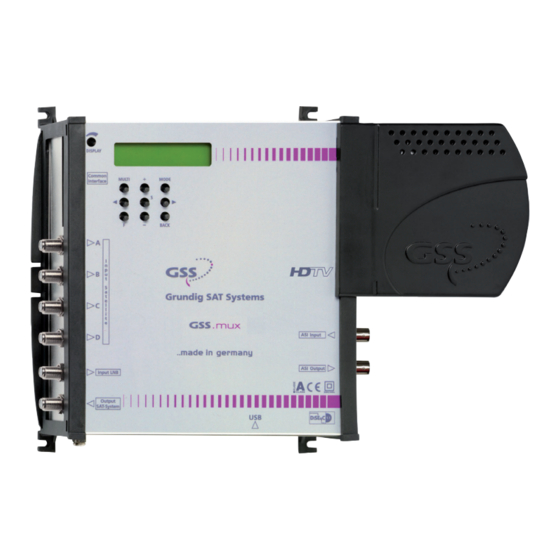
3.2 d e v i C e ov e rv i e w Assembling slots PE connection terminal Display Display contrast control Operating buttons Slot for CA module Micro USB socket (update) SAT tuner inputs A…D Loop through input (LNB) SAT IF output ASI input ASI output... - Page 13 f r e e i n P u t ava i l a b l e t h e m u lt i s w i tC h • Connect the SAT IF output to a free input of the multiswitch. •...
- Page 14 —> If you would like to integrate the device to an existing plant, now first you should connect it to the mains and perform all settings (page 23). Therefore especially observe the notes on frequency set- ting (page 20) and level setting (page 22). •...
- Page 15 3.4 r Ca e t r o f i t t i n g m o d u l e The device is equipped with a common interface. It allows you to connect a CA module for various scrambling systems and service providers. Scrambled channels can only be descrambled with a CA module suitable for the scram- bling system and the corresponding smart card.
-
Page 16: Software
Do not disconnect the USB connection during instal- lation! • Use the device manager to identify the COM port, which is assigned to the SMCIP 401 ASI. —> In this example – the new added port COM4. - 16 -... - Page 17 • Start the "BE-Flash" application (BEflash.exe) and select the corresponding interface (COM port). • Click on button • Select the .hex file you had unpacked before and click on button • Click on button —> The update progress is displayed. - 17 - SMCIP 401 ASI...
- Page 18 • Close the "BE-Flash" application. • Uninstall the COM port driver from the device manager after the update is finished successfully! —> Active the COM port driver (in this example COM4). Select in menu Action or via the context menu the menu item Uninstall. • Disconnect the USB connection. - 18 - SMCIP 401 ASI...
-
Page 19: The Control Panel At A Glance
C o n t r o l P a n e l g l a n C e 4.1 C o n t r o l Pa n e l The key pad on the device is used to scroll through the menus step-by-step: MODE scrolls forward through the menus BACK... - Page 20 r o g r a m m i n g 5.1 n ot es f r e q u e n C y s e t t i n g If you fit in the "new" transponder to an existing SAT IF range, you have to set the output frequency to a gap (or the beginning/end) of the spectrum.
- Page 21 • Feed the SAT IF range, in which you would like to insert the "new" trans- ponder, into the device via LNB input • Connect a SAT IF spectrum measurement device to output • Graph the spectrum which is present at the device output with a measur- ing instrument and adjust the output frequency of the "new"...
- Page 22 5.2 n ot es l e v e l s e t t i n g Equalize the output level of the device (menu "OUTPUT") to the levels of the other transponders, in order not to overdrive downstreamed multiswitches/ amplifiers. e v e l to o h i g h...
- Page 23 5.3 P ro g r a m m i n g Pro C e d u r e Page 24 DVB-S => DVB-S Ein / On Bedienhinweise Operating Hints – – – – "blättert" Menüs vorwärts scrolls forward through the menu abcd = kein/no Signal "blättert"...
- Page 24 OVER 28 / 54.8 OVER = Overflow TS/ONID 0x0800 0x0000 CA-MODE Data –> CA 204/188 Bit 01/05 MENU PID Check Vid => Information *) Page 23 off / Vid / All nur mit CA-Modul/ onlywith CA module *) Die angezeigte Information ist abhängig vom verwendeten CA-Modul.
- Page 25 tat u s m e n u DVB-S => DVB-S – – – – By default no stations are selected in menu station selection –> indication "– – – –". The software version is displayed on the right (e.g. V 8). If stations are selected in menu station selection, it is displayed whether the tuners A…D are "locked"/"not locked"...
- Page 26 u t P u t m o d e The output transport stream is transferred to the ASI output as well as to the modulator. The maximum possible output data rate is dependent on the DVB-S output parameter settings (max. 72.573 Mbit/s)! If only the ASI output is needed, the modulator can be switched off.
- Page 27 (sat if) o d u l ato r f r e q u e n C y In this menu you adjust the output frequency of the modulator. DVB-S FREQ 1745 MHz • Using buttons </> to select the cursor position for the frequency setting. •...
- Page 28 Spectral position – inverting the user signal For exceptional cases and "older" digital receivers, the spectral position of the user signal can be inverted "NEG". The default setting is "POS". • Use </> to place the cursor under "POS". • Use +/– to set the spectral position to "NEG". Code rate (FEC): —>...
- Page 29 MODE • Press the button. —> The "input parameter" menu – "INPUT" is activated. n P u t Pa r a m e t e r In this menu you select the input (tuner "A"…"D" resp. ASI "D") for which you would like to do the input settings in the related submenus.
- Page 30 Example: S10Hh means Satellite 10 (DiSEqC position 10), Horizontal high —> The control voltage only serves to control multiswitches and is not suitable for power supply of upstreamed components (maximum load 65mA). —> GSS Multiswitches must be triggered by the following DiSEqC co- mands: Input group A —> DiSEqC command S01 Input group B —> DiSEqC command S02 Input group C —>...
- Page 31 n P u t s ym b o l r at e In this menu you set the symbol rate of the desired transponder in kSymb/s. SYMBOL 22000 8PSK 2/3 The symbol rates of the satellite transponders can be found in the current chan- nel table of the satellite operator, in various satellite magazines and in the Internet.
- Page 32 • Press +/– to set the respective digit of the input frequency needed. • Repeat the procedure by the quantity of the digits to be set. • Set the frequency offset shown in the display (e.g. "– 1.8") to less than 1 MHz ("± 0.x") by varying the input frequency using the +/–...
- Page 33 —> The display shows e.g.: A TV + 01/14 ORF SPORT+ Meaning of the indicators in the example: "A" Tuner "A" "TV" TV channel type " + " The currently selected station is switched on. "01/14" The 1st of 14 stations is being displayed. "ORF SPORT+" Station name Further possible terms displayed: "RA" Radio channel type For radio stations, the background of the screen of the connected TV or test receiver is darkened.
- Page 34 —> The "Output data rate" – "DATARATE" main menu is activated. u t P u t data r at e This menu shows the maximum possible output data rate and the current need- ed output data rate in MBit/s. The current needed output data rate. DATARATE 72.5: Maximum output data rate (dependent on...
- Page 35 id orgnet-id r a n s P o r t s t r e a m a n d If a completely new, additional transponder is generated, IDs (ORGNET-IDs) must be assigned to it, in order that a station search of connected SetTopBoxes can be performed faultlessly.
- Page 36 Pid m o n i to r i n g In this menu you can switch off the PID monitoring and call up a menu for the settings of the CA module (dependent on the CA module). PID Check Vid =>...
- Page 37 m o d u l e The menu varies according to which CA module you are using. For this rea- son, please refer to the operating manual of your particular CA module. The relevant information is shown in the display of the device. This may appear as a fixed display or as scrolling text according to display capabilities.
- Page 38 aC to ry r es e t In this menu you can reset all settings to the factory defaults. FACTORY FACTORY Defaults => STORE => S • Press the > button. —> The factory defaults are invoked. —> By pressing the MODE button, you will be returned to the menu item "Output settings"...
- Page 39 Phone: +49 (0) 911 / 703 8877 • Fax: +49 (0) 911 / 703 9210 www.gss.de/en • info@gss.de CLASS CLASS Service: Phone: +49 (0) 911/703 2221; Fax: +49 (0) 911/703 2326; service@gss.de Alterations reserved. Technical data E. & O.E. © by GSS Grundig Systems GmbH V8/001/2017...
Need help?
Do you have a question about the SMCIP 401 ASI and is the answer not in the manual?
Questions and answers