Table of Contents
Advertisement
Quick Links
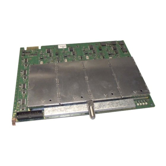
STC 160 Head-End Station
Notes on the Assembly Instructions.
As well as this supplementary Assembly
Instructions, the Assembly Instructions for the
STC 160 apply.
GSS
Grundig SAT Systems GmbH
Beuthener Strasse 43
D-90471 Nuremberg
Quad modulators
HMM 480 / HMM 480 OIRT
Phone:
Fax:
Email:
Internet:
HMS 480
+49 (0) 911 / 703 8877
+49 (0) 911 / 703 9210
info@gss.de
www.gss.de
Advertisement
Table of Contents

Related Manuals for GSS HMS 480


Summary of Contents for GSS HMS 480
- Page 1 STC 160 Head-End Station Quad modulators HMS 480 HMM 480 / HMM 480 OIRT Notes on the Assembly Instructions. As well as this supplementary Assembly Instructions, the Assembly Instructions for the STC 160 apply. Phone: +49 (0) 911 / 703 8877...
-
Page 2: Table Of Contents
Setting the output level ..............14 Selecting the audio signal ..............15 Storing data ..................15 6 Final procedures ....................16 7 Channel and frequency tables ................17 - 2 - HMM 480 / HMM 480 OIRT / HMS 480... -
Page 3: Safety Regulations
C o p e o f d e l i v e ry 1 HMM 480, HMM 480 OIRT or HMS 480 module 1 HF cable with F plugs 1 Brief Assembly Instructions - 3 - HMM 480 / HMM 480 OIRT / HMS 480... -
Page 4: Meaning Of The Symbols Used
Unless otherwise noted all values are specified as "typical". HF outputs Modulators A / B / C / D: Channels: HMM 480 / HMS 480 ......PAL B/G; C 02…C 69, S 03…S 41 HMM 480 OIRT ....PAL D/K; R 01…R 12; s 01…s 38, C 21…C 69 Frequency range: HMM 480 / HMS 480 ........48.25 MHz…855.25 MHz HMM 480 OIRT ..........49.75 MHz…855.25 MHz... -
Page 5: Description
"BE-Flash" and the current assembly instructions on the website "www.gss.de". The modulator module is designed exclusively for use in the STC 160 head- end station. - 5 - HMM 480 / HMM 480 OIRT / HMS 480... -
Page 6: Installation
The open slot in between (without a contact strip on the board at the rear wall of the housing) is intended for an add- on module. - 6 - HMM 480 / HMM 480 OIRT / HMS 480... -
Page 7: Connecting The Modulator Module
• After programming, connect the modulator output to one of the input sockets on the output collector. • Close the locking device in the direction of the arrow. —> Ensure that the ground spring gets contact to the locking device. - 7 - HMM 480 / HMM 480 OIRT / HMS 480... -
Page 8: The Control Panel At A Glance
C t i o n s o f t h e C o n t r o l pa n e l b u t to n s To move the cursor To adjust values and functions To save the programmed data To switch to the next menu - 8 - HMM 480 / HMM 480 OIRT / HMS 480... -
Page 9: Programming
—> Always all modulator modules are set. Mixed operation is not possible! To operate the HMM 480 OIRTmodule the software version of the control unit (head-end station) must be “V 9” or higher. - 9 - HMM 480 / HMM 480 OIRT / HMS 480... -
Page 10: Programming Procedure
0 … -15 dB Level 0 dB HMM 480 Bx 2A AUDIO Stereo / Dual / DUAL STEREO STEREO Bx 2A MEMORY Bx 1A S => STORE CANCEL - 10 - HMM 480 / HMM 480 OIRT / HMS 480... -
Page 11: Programming The Modulator Module
—> Always all modulator modules are set. Mixed operation is not possible! To operate the HMM 480 OIRTmodule the software version of the control unit (head-end station) must be “V 9” or higher. - 11 - HMM 480 / HMM 480 OIRT / HMS 480... -
Page 12: Selecting The Module / Channel Strip
Bx 2A OUTPUT Modulator • Use the buttons to switch "on" the modulator (LED illuminates – page 9), or to switch "off" the modulator if necessary (LED is switched off). - 12 - HMM 480 / HMM 480 OIRT / HMS 480... -
Page 13: Selecting Channel / Frequency Setting
Only change the fine tuning (frequency offset) in circumstances where it is absolutely necessary to do so. Once you have changed it, all televisions con- nected to the cable system will need to be calibrated by means of fine tuning to match it. - 13 - HMM 480 / HMM 480 OIRT / HMS 480... -
Page 14: Setting The Output Frequency
Bx 2A OUTPUT Level 0 dB • Use the test receiver to measure the output level of the channel strip and make note of the value. • When adjusting the other channel strip, compare its value with the value noted for the first channel strip. • Measure the output levels of the other modulators used and make notes of their values. - 14 - HMM 480 / HMM 480 OIRT / HMS 480... -
Page 15: Selecting The Audio Signal
C t i n g t h e au d i o s i g n a l In this menu, you can select when using – HMS 480 between the audio settings "STEREO" or "DUAL" or when using – HMM 480 / OIRT between mono audio (Mono L) and the composite signal of the audio signals (Mono L + R). -
Page 16: Final Procedures
• Test the output level of the output collector according to the STC 160 assem- bly instructions and set the output level required for the cable system. • Mount the base plate and the front cover (see STC 160 assembly instruc- tions). - 16 - HMM 480 / HMM 480 OIRT / HMS 480... -
Page 17: Channel And Frequency Tables
847.25 C 29 535.25 C 39 615.25 C 49 695.25 C 59 775.25 C 69 855.25 C 30 543.25 C 40 623.25 C 50 703.25 C 60 783.25 - 17 - HMM 480 / HMM 480 OIRT / HMS 480... - Page 18 831.25 215.25 423.25 631.25 839.25 223.25 431.25 639.25 847.25 231.25 439.25 647.25 855.25 239.25 447.25 655.25 247.25 455.25 663.25 255.25 463.25 671.25 263.25 471.25 679.25 271.25 479.25 687.25 - 18 - HMM 480 / HMM 480 OIRT / HMS 480...
- Page 19 CE - Declaration of Conformity - 19 - HMM 480 / HMM 480 OIRT / HMS 480...
- Page 20 - 20 - HMM 480 / HMM 480 OIRT / HMS 480...
- Page 21 - 21 - HMM 480 / HMM 480 OIRT / HMS 480...
- Page 22 Service: Phone: +49 (0) 911 / 703 2221 Fax: +49 (0) 911 / 703 2326 Email: service@gss.de Alterations reserved. Technical data E. & O.E. © by GSS GmbH 15082011...
Need help?
Do you have a question about the HMS 480 and is the answer not in the manual?
Questions and answers