GSS STC 160 Assembly Instructions Manual
Head-end station, head-end digital modulator
Hide thumbs
Also See for STC 160:
- Assembly instructions manual (12 pages) ,
- Assembly instructions manual (28 pages) ,
- Assembly instructions manual (8 pages)
Table of Contents
Advertisement
Quick Links
STC 160 Head-End Station
Head-End Digital Modulator
Notes on the Assembly Instructions.
As well as this supplementary Assembly
Instructions, the Assembly Instructions for the
STC 160 apply.
GSS
Grundig SAT Systems GmbH
Beuthener Strasse 43
D-90471 Nuremberg
Grundig SAT Syst ms
HDM 565 C
Phone:
+49 (0) 911 / 703 8877
Fax:
+49 (0) 911 / 703 9210
Email:
info@gss.tv
Internet:
www.gss.tv
Advertisement
Table of Contents

Related Manuals for GSS STC 160


Summary of Contents for GSS STC 160
- Page 1 Grundig SAT Syst ms STC 160 Head-End Station Head-End Digital Modulator HDM 565 C Notes on the Assembly Instructions. As well as this supplementary Assembly Instructions, the Assembly Instructions for the STC 160 apply. Phone: +49 (0) 911 / 703 8877...
-
Page 2: Table Of Contents
Contents 1 Safety regulations ....................3 2 General information .................... 3 2.1 Scope of delivery .................. 3 2.2 Technical data ..................4 2.3 Description ................... 5 3 Installation ......................6 3.1 Installing the QPSK-QAM module ............6 3.2 Connecting the QPSK-QAM module ............7 4 The control panel at a glance ................ -
Page 3: Safety Regulations
Safety regulations Please read the safety regulations listed in the assembly instructions for the STC 160 head-end station which pertain to this module. When working on the modules, please take measures to protect against ESD! General information 2.1 Scope of delivery... -
Page 4: Technical Data
2.2 Technical data The requirements of the following EU directives are met: 73/23/EEC, 89/336/EEC The product fulfils the guidelines and standards for CE labelling. HF input: Frequency range: 910 … 2150 MHz Input level: 60 dBμV … 80 dBμV Input impedance: typ. -
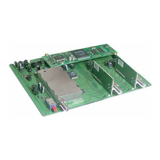
Page 5: Description
Flash”) using a PC or notebook via the 9-pin SUB-D socket on the head-end station. You can find the current operating software for the QPSK-QAM module on the website “www.gss.tv”. The QPSK-QAM module is designed exclusively for use in the STC 160 head- end station. - 5 -... -
Page 6: Installation
Take measures to protect against ESD! • Open the housing of the head-end station in accordance with the assembly instructions for the STC 160. 3.1 Installing the QPSK-QAM module Caution –... -
Page 7: Connecting The Qpsk-Qam Module
3.2 Connecting the QPSK-QAM module • Connect SAT-IF inputs on the QPSK-QAM module with the correspond- ing cable terminals or with one of the outputs (if applicable) on the retro- fitted SAT IF input distributor. • After programming, connect the modulator output with one of the input sockets on the output collector. -
Page 8: The Control Panel At A Glance
The control panel at a glance 4.1 Menu items Program the QPSK-QAM module using the buttons on the head-end station con- trol panel. The menus appear on the two-line display of the control panel. The parameters and functions to be set are underlined. You can use the M button to select the following menu items: –... -
Page 9: Programming
Programming 5.1 Preparation • Connect the test receiver to the HF output on the QPSK-QAM module or to the HF output on the output collector if it is already connected (page 7). • Adjust the test receiver to the output channel of the channel strip to be set. •... -
Page 10: The Menus At A Glance
5.3 The menus at a glance Ein/On SETUP BE160 Bx 1A TWIN-SAT Böx 4 TWIN-SAT Bx 1A Bx 1B C5-12,S3-24 C5-12,S3-24 Bx 1A OUTPUT Channel Channel / Freq. Bx 1A OUTPUT S21 / S22 on / off Bx 1A LEVEL 0 dB control control / random... - Page 11 Bx 1A MEASURE SR=6875 (6605) Bx 1A MEMORY S => STORE CANCEL - 11 - - 11 -...
-
Page 12: Programming The Qpsk-Qam Module
—> The display shows “SETUP BE160” and the software version of the head-end station (e.g. V 5). —> In the “SETUP” menu, the output level of the output collector can be adjusted (see STC 160 assembly instructions). Ein/On Ein/On SETUP... -
Page 13: Selecting Channel / Frequency Setting
—> With the exception of a few minor differences, the programming procedure is the same for channel strips “A” and “B”. These minor differences are men- tioned in the respective chapters. • Press the button. —> The “Selecting channel/frequency setting” menu – “OUTPUT”... -
Page 14: Setting The Output Channel
Bx 1A Bx 1A OUTPUT OUTPUT Channel Channel Channel / Freq. Channel / Freq. • Use to select channel setting “Channel” or frequency setting “Freq.” (see page 15). • Press the button. —> The “Setting the output channel” – “OUTPUT” menu is activated. -
Page 15: Setting The Output Frequency
Setting the output frequency Bx 1A OUTPUT 306.0 / 314.0 • Use to position the cursor under the digit to set for the frequency display then use to set the output fre- quency wished. Switching on/off the channel strip output •... -
Page 16: Adjusting The Output Levels Of The Channel Strips
Adjusting the output levels of the channel strips In this menu, the “control” setting is used to transmit a digital carrier through the analogue video carrier frequency of the output channel for the respective channel strip. This makes it possible to measure the absolute output level of this channel strip with an analogue test receiver. -
Page 17: Setting The Lnb Oscillator Frequency
Setting the LNB oscillator frequency Bx 1A Bx 1A f = 10600 MHz f = 10600 MHz • Use the buttons to position the cursor under the digit to be set, then use to set the oscillator frequency for the LNB being used. •... -
Page 18: Setting The Input Frequency
Setting the input frequency Notes: – Once the HF receiver has synchronised to the input signal, any offset to the target frequency is displayed in MHz, e.g. “+0.2”. – The “CN…” indicator in this menu provides an indication of the C/N signal-to-noise ratio of the received carrier. If the value is below “CN 5,”... -
Page 19: Setting The Qam Modulation
• Press the button. —> The “Setting the QAM modulation” – “QAM” menu is activated. Setting the QAM modulation In this menu, you can set the QAM modulation and invert the user signal. Bx 1A Bx 1A normal normal normal / inverse normal / inverse •... -
Page 20: Measuring The Output Symbol Rate
Measuring the output symbol rate Bx 1A Bx 1A MEASURE MEASURE SR=6875 (6605) SR=6875 (6605) SR=6875 (= “number 1”): Real output symbol rate Bx 1A MEASURE SR=6875 (6605) Number 1 Number 2 (6605) (= “number 2”): Current measured symbol rate of the station. -
Page 21: Saving Data
Saving data Bx 1A Bx 1A MEMORY MEMORY S => STORE S => STORE CANCEL CANCEL • All programmed data is saved by pressing the S but- ton. You will be returned to the menu item “Selecting the module / channel strip” via (page 12). -
Page 22: Channel And Frequency Tables
778.00 C 32 562.00 C 46 674.00 C 60 786.00 C 33 570.00 C 47 682.00 C 61 794.00 C 34 578.00 C 48 690.00 C 62 802.00 Alterations reserved. Technical data E. & O.E. © by GSS GmbH 04122007...
Need help?
Do you have a question about the STC 160 and is the answer not in the manual?
Questions and answers