Winmate FM10 Quick Start Manual
Vehicle mounted computer microsoft windows 7 professional for embedded system/ embedded 8.1 industry pro
Hide thumbs
Also See for FM10:
- User manual (73 pages) ,
- Product reference manual (72 pages) ,
- Quick start manual (17 pages)
Table of Contents
Advertisement
Quick Links
Winmate FM10
Vehicle Mounted Computer
®
Microsoft
Windows
®
Microsoft
Windows
Quick Start Guide
For more information on this and other
Winmate products, please visit our
website at:
www.winmate.com
Document Version 4.0
Document Part No.9152111I100S
®
7 Professional for Embedded System
®
Embedded 8.1 Industry Pro
Advertisement
Table of Contents

Subscribe to Our Youtube Channel
Related Manuals for Winmate FM10


Summary of Contents for Winmate FM10
- Page 1 ® Microsoft Windows 7 Professional for Embedded System ® ® Microsoft Windows Embedded 8.1 Industry Pro Quick Start Guide For more information on this and other Winmate products, please visit our website at: www.winmate.com Document Version 4.0 Document Part No.9152111I100S...
-
Page 2: Table Of Contents
Contents Unpacking a. Standard Package Content b. Optional Accessories II. Components III. Docking and Undocking the Device a. Docking the device into vehicle dock b. Undocking the device IV. Cabling Installation a. Connecting the power cable for office testing b. Connecting the power cable on the vehicle V. - Page 3 Warranty Winmate Inc. warrants that each of its products is free from material and workmanship defect for a period of one year starting from the invoice date. If the customer discovers a defect, Winmate Inc.
- Page 4 FCC Regulations This device complies with part 15 of the FCC Rules. Operation is subject to the following two conditions: (1) This device may not cause harmful interference, and (2) this device must accept any interference received, including interference that may cause undesired operation. This device has been tested and found to comply with the limits for a Class B digital device, pursuant to Part 15 of the FCC Rules.
- Page 5 IC Regulations Le présent appareil est conforme aux CNR d’Industrie Canada applicables aux appareils radio exempts de licence. L’exploitation est autorisée aux deux conditions suivantes: l’appareil ne doit pas produire de brouillage, et l’utilisateur de l’appareil doit accepter tout brouillage radioélectrique subi, même si le brouillage est susceptible d’en compromettre le fonctionnement.”...
-
Page 6: Unpacking
Before using this device, make sure that all the items listed below are present in your package: Dock + Latch 5 m Power Cable with 0.15 m Power Computer FM10 0.3 m USB Cable Locking Key Fuse Kit Converter Cable... -
Page 7: Optional Accessories
Antenna (VM9C) (VM240) (VM10S) 9BRFID000012 39700000000M 39700000000N 39700000000U 98K000A0005Y Mounting Kit 3 Mounting Kit 2 Keyboard Stylus Kit + Screw Drill Mounting 98K000A0006P 98K000A0005X 98K000A0005T It is highly recommended to purchase a power cable from Winmate for Note testing purposes... -
Page 8: Components
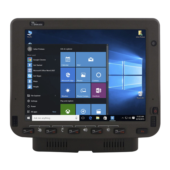
Components Front View The integrated keypad contains 10 programmable keys, the F1 through F10 keys are user programmable. Key mapping is configured via the hot tab option in the control panel. See programmable key to remap these keys. The default values for these keys are: Press these keys in order Default Key Value F1 + F2... - Page 9 Rear View with Vehicle Dock Left Side View with Vehicle Dock Right Side View with Vehicle Dock...
-
Page 10: Docking And Undocking The Device
III. Docking and Undocking the Device a. Docking the device into vehicle dock To dock the device, perform the following: 1. With the device screen side facing out, align and insert the device into the guide pins on the vehicle dock. 2. -
Page 11: Cabling Installation
Wiring Instruction 1. Place the device on the vehicle dock and make sure the device is Off. 2. Connect the CN2 to the FM10 vehicle dock by aligning the connector pins and then push it, twist to fasten the connection. -
Page 12: Connecting The Power Cable On The Vehicle
b. Connecting the power cable on the vehicle This power cable should only be used on the 12, 24, 36, or 48 Volt Warning forklifts. Warning Select a mounting location and make sure it is not located on the outside the vehicle Warning Do not perform the installation on a moving or live electric forklift Warning All power wiring must use the supplied power cable Wiring Instruction... -
Page 13: Power On Behavior
Fuse Specification : Two Fuses , 15A, 250Volt, UDA Type Fuses 4. Slide tubing over wires, remove the wires and insert it to the fuse holder, crimp it. wire to the vehicle’s positive power source. Connect the black wire to 5. -
Page 14: Power Button
The Power button is located at lower right of the FM10 Note • The FM10 need to be docked in a powered vehicle dock or UPS battery has a sufficient charge to power on the device. • If no external power available and the UPS... -
Page 15: Standby / Wakeup Behavior
b. Standby / Wakeup Behavior Power Button Action Button Indicator Backlight Press the On button for “2 seconds” until the screen On and Standby or then release the button. The Sleep battery indicator will Off after the Mode screen is Off, the system is already in the standby / sleep mode Press the On button for “2... -
Page 16: Calibrating The Screen
Calibrating the Screen Where there is a noticeable discrepancy in the placement of the stylus on the screen and the indicated position of the on screen pointer, recalibrate the screen. Long press F2 function key to call the Screen Calibration menu. Follow the instructions on screen calibration starting from #2. -
Page 17: Defroster
VII. Defroster The defroster is always disable when the device is operating Warning from UPS battery power 1. To show the defroster status tap and this screen below shows the information about the defroster. 2. The default status of Defroster is Disabled. 3. - Page 18 4. To trigger the Defroster OFF, the Defroster off trip point needs to be in between 5 deg. C and 10 deg. C. The defroster off trip point is configurable as follow: When the Defroster is OFF, a heater indicator in the lower right corner of the device will Turn off Example: In this example “5 deg.
-
Page 19: Antenna Installation
VIII. Antenna Installation The FM10 vehicle dock is equipped with SMA Connector for additional external antenna (Wi-Fi or optional WWAN), to install the antenna please perform the following: 1. Remove the rubber cap on the SMA connector before installing the antenna. -
Page 20: Ram Mounts Installation
The docking of this device is designed to be mounted to RAM Mount solutions, which provides various types of mount types to fit any industrial use or vehicle. Each mounting kit consists of: No Component Winmate Part RAM Mounts Description Quantity... -
Page 21: Ram Mounts Assembly
b. RAM Mounts Assembly Step 1 Install RAM Clamp to vehicle or forklift 1.1 Determine the position for mounting the RAM clamp mount according to RAM Mounts installation guide and specification. 1.2 Place the upper clamp with ball on the beam, insert the bolt. 1.3 Place the lower clamp below the beam;... -
Page 22: Keyboard Mounting Installation
(Length:8.375”) RAM Ball on the device 75x75mm VESA 9B000000007U RAM-D-2461U with 2.25” Ball side 4 VESA Holes on Winmate Keyboard adapter the plate to plate (designed by 821009131600 device and 4 Winmate) AMPS holes to RAM Ball RAM Ball on the sloped 2.5"... - Page 23 This part shows the steps to install the keyboard. 1. Fasten all four screws on the RAM mount ball on the back of the keyboard 2. Fasten the keyboard adapter on the other end of the RAM mount ball. 3. Fasten the RAM mount ball screws on the back of the device, so all mounting parts are fasten together.
- Page 24 Winmate Inc. 9F, No.111-6, Shing-De Rd., San-Chung District, New Taipei City 24158, Taiwan, R.O.C Tel: 886-2-8511-0288 Fax: 886-2-8511-0211 Email: sales@winmate.com.tw Official website: www.winmate.com...
Need help?
Do you have a question about the FM10 and is the answer not in the manual?
Questions and answers