
Related Manuals for Newport ILX Lightwave LDC-3926


Summary of Contents for Newport ILX Lightwave LDC-3926
- Page 1 sales@artisantg.com artisantg.com (217) 352-9330 | Visit our website - Click HERE...
- Page 2 User’s Guide High Power Laser Diode Controller Mainframe LDC-3926 ILX Lightwave Corporation · 31950 Frontage Road · Bozeman, MT, U.S.A. 59715 · U.S. & Canada: 1-800-459-9459 · International Inquiries: 406-556-2481 · Fax 406-586-9405 · ilx.custhelp.com www.ilxlightwave.com 70035601 January 2010...
-
Page 4: Table Of Contents
Table of Contents List of Figures........... . v List of Tables. - Page 5 Table of Contents Chapter 2 Operations Front Panel Controls ..........8 Display Section Controls .
- Page 6 Table of Contents Command Syntax ..........25 Letters .
- Page 7 Table of Contents LDC-3926...
-
Page 8: List Of Figures
List of Figures Figure 1.1 Front Panel ......... 4 Figure 1.2 Mainframe Rear View . - Page 9 List of Figures LDC-3926...
-
Page 10: List Of Tables
List of Tables Table 1.1 General Specifications ........5 Table 3.1 Substitute Parameter Names. - Page 11 List of Tables viii LDC-3926...
-
Page 12: Safety And Warranty Information
AFETY AND ARRANTY NFORMATION The Safety and Warranty Information section provides details about cautionary symbols used in the manual, safety markings used on the instrument, and information about the Warranty including Customer Service contact information. Safety Information and the Manual Throughout this manual, you will see the words Caution and Warning indicating potentially dangerous or hazardous situations which, if not avoided, could result in death, serious or minor injury, or damage to the product. -
Page 13: Safety Symbols
S A F E T Y S Y M B O L S AFETY YMBOLS This section describes the safety symbols and classifications. Technical specifications including electrical ratings and weight are included within the manual. See the Table of Contents to locate the specifications and other product information. The following classifications are standard across all ILX Lightwave products: •... -
Page 14: Warranty
WA R R A N T Y ARRANTY ILX LIGHTWAVE CORPORATION warrants this instrument to be free from defects in material and workmanship for a period of one year from date of shipment. During the warranty period, ILX will repair or replace the unit, at our option, without charge. Limitations This warranty does not apply to fuses, lamps, defects caused by abuse, modifications, or to use of the product for which it was not intended. -
Page 15: Comments, Suggestions, And Problems
WA R R A N T Y Comments, Suggestions, and Problems To ensure that you get the most out of your ILX Lightwave product, we ask that you direct any product operation or service related questions or comments to ILX Lightwave Customer Support. - Page 16 WA R R A N T Y When you contact us, please have the following information: Model Number: Serial Number: End-user Name: Company: Phone: Fax: Description of what is connected to the ILX Lightwave instrument: Description of the problem: If ILX Lightwave determines that a return to the factory is necessary, you are issued a Return Authorization (RA) number.
- Page 17 WA R R A N T Y LDC-3926...
-
Page 18: Introduction And Specifications
C H A P T E R NTRODUCTION AND PECIFICATIONS Chapter 1 is an introduction to the LDC-3926 Laser Diode Controller. It contains unpacking information, installation instructions, and basic instruction about how to apply power. It also contains some maintenance information and specifications. If any of the following symptoms exist, or are even suspected, remove the LDC-3926 from service. -
Page 19: Initial Inspection
I N T R O D U C T I O N A N D S P E C I F I C A T I O N S C H A P T E R Installing the LDC-3926 Initial Inspection Visually inspect the mainframe and its packaging for damage or signs of mishandling. -
Page 20: Rs-232 Connectors
I N T R O D U C T I O N A N D S P E C I F I C A T I O N S C H A P T E R Installing the LDC-3926 RS-232 Connectors The RS-232 interface consists of two 9-pin, D-sub connectors, located on the rear panel (see Figure 1.2 on page 4). -
Page 21: Front And Back Panels
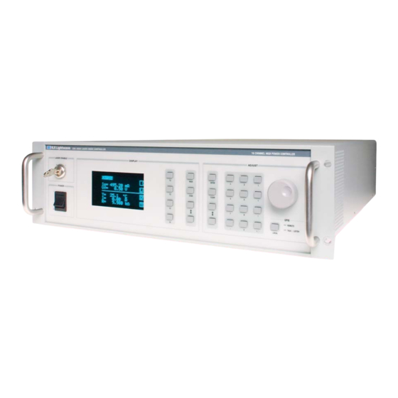
I N T R O D U C T I O N A N D S P E C I F I C A T I O N S C H A P T E R Front and Back Panels Front and Back Panels Figure 1.1 and Figure 1.2 show front and rear views of the instrument. -
Page 22: Specifications
I N T R O D U C T I O N A N D S P E C I F I C A T I O N S C H A P T E R Specifications Specifications The LDC-3926 is factory configured with a 20 A mains fuse for regions or locations with a nominal line voltage of 100 VAC and 15 A mains fuse for regions with nominal line voltages of 120, 200-240 VAC. - Page 23 I N T R O D U C T I O N A N D S P E C I F I C A T I O N S C H A P T E R Specifications LDC-3926...
- Page 24 C H A P T E R PERATIONS This chapter introduces you to the operation of the LDC-3926. It offers instructions for connecting your laser to the current source and temperature control modules and describes powering up the instrument. The chapter also provides a description of the front panel controls, including both display and adjust controls.
-
Page 25: Operations
O P E R A T I O N S C H A P T E R Front Panel Controls Front Panel Controls All key operating parameters for the laser and temperature control modules can be set, adjusted, and displayed through established menus. See the respective module manual for further information on each module. -
Page 26: Soft Keys
O P E R A T I O N S C H A P T E R Front Panel Controls Soft Keys The four keys closest to the display window are used as soft keys. They perform menu-specific functions within each menu. When you have accessed a menu, the soft key identification for this menu appears on the right side of the display, next to the corresponding key. -
Page 27: Applying Power To The Mainframe
O P E R A T I O N S C H A P T E R Applying Power to the Mainframe decreases the number via a time-based acceleration algorithm. When the Arrow keys are pressed, the new values are updated automatically. Numeric Keypad Enter and... -
Page 28: The Power On State
O P E R A T I O N S C H A P T E R Using the Menu Structure The Power On State The controller defaults to the Channel menu and the first channel with a module when power is applied. -
Page 29: Channel Menu
O P E R A T I O N S C H A P T E R Using the Menu Structure Channel Menu The Channel menu provides standard user information, along with soft-key assignments for configuring a module further or for turning the output On or Off. Pressing the CHAN key allows you to jump directly to the default Channel menu. -
Page 30: Communications Configuration
O P E R A T I O N S C H A P T E R Using the Menu Structure Communications Configuration To operate your LDC-3926 remotely, via the General Purpose Information Bus (GPIB) or through a serial RS-232 link, select Comm. from the System Configuration menu to access the Config. Comm menu. -
Page 31: Calibration
O P E R A T I O N S C H A P T E R Using the Menu Structure keys to turn the Adjust Knob on or off. Press ENTER after making the desired selection to execute the change. Enter Key INC/DEC Keys Figure 2.9 Display Configuration Menu... -
Page 32: Save And Recall
O P E R A T I O N S C H A P T E R Using the Menu Structure Save and Recall The Save and Recall feature is used to alternate between particular instrument configurations. The Save feature allows you to store front panel settings for any given configuration. These settings, which are stored in one of ten memory bins, are retrieved at any time with the Recall function. -
Page 33: All Channel Menu
O P E R A T I O N S C H A P T E R Using the Menu Structure All Channel Menu The All Channel menu allows you to configure all 16 channels of the instrument (or any number of channels from 2 to 16) simultaneously. -
Page 34: Status Menu
O P E R A T I O N S C H A P T E R Using the Menu Structure Status Menu The Status menu allows you to view information about module status, adjust setpoints, turn on outputs and view module error codes. There are two status pages to choose from: •... -
Page 35: Displaying The Status Screen
O P E R A T I O N S C H A P T E R Using the Menu Structure Displaying the Status Screen The Status screen provides instant access to multiple channel status information. You can also change laser and TEC setpoints and turn on the laser or TEC from the status screen. Press the Status soft key (F4) from the Status menu. -
Page 36: Modulating The Laser Current Sources
O P E R A T I O N S C H A P T E R Using the Menu Structure Modulating the Laser Current Sources The LDC-3926 allows a modulated signal to be superimposed on the laser current of any or all current source modules. - Page 37 O P E R A T I O N S C H A P T E R Using the Menu Structure LDC-3926...
-
Page 38: Remote Operations
C H A P T E R EMOTE PERATIONS GPIB (General Purpose Interface Bus) is the common name for ANSI/IEEE Standard 488.2-1987, an industry standard for interconnecting test instruments in a system. Everything you can do from the front panel can also be done remotely, and in some cases, with more flexibility. For instance, in remote mode you have access to commands for functions not found on the front panel. -
Page 39: Gpib Cable Connections
R E M O T E O P E R A T I O N S C H A P T E R GPIB Configuration GPIB Cable Connections Standard GPIB connectors can be linked together (daisy-chained), allowing you to configure the system linearly or in a star configuration. -
Page 40: Reading The Gpib Address
R E M O T E O P E R A T I O N S C H A P T E R GPIB Configuration DIO1 DIO5 DIO2 DIO6 DIO3 DIO7 DIO4 DIO8 GND (Twisted pair with DAV) NRFD GND (Twisted pair with NRFD) NDAC GND (Twisted pair with NDAC) GND (Twisted pair with IFC) -
Page 41: Rs-232 Configuration
R E M O T E O P E R A T I O N S C H A P T E R GPIB Configuration RS-232 Configuration The baud rate setting must match the baud rate used by the serial RS-232 interface, which is typically a serial COMM port on your PC. -
Page 42: Gpib Vs. Rs-232 Communications
R E M O T E O P E R A T I O N S C H A P T E R Mainframe Command Set GPIB vs. RS-232 Communications The LDC-3926 must not be run remotely via GPIB and RS-232 at the same time. When using the RS-232 interface, the remote GPIB command set is fully operable. -
Page 43: Terminators
R E M O T E O P E R A T I O N S C H A P T E R Mainframe Command Set A query has no space between the mnemonic and the question mark. For example: Okay Not Okay TIMER? -
Page 44: Table 3.1 Substitute Parameter Names
R E M O T E O P E R A T I O N S C H A P T E R Mainframe Command Set There are no default values for omitted parameters. If a command is expecting a parameter and none is entered, an error is generated. -
Page 45: Command Tree Structure
R E M O T E O P E R A T I O N S C H A P T E R Mainframe Command Set Command Tree Structure The LDC-3926 commands require the full path notation. (root) Module-specific commands: Commands Generic Module Commands see the module instruction manual... -
Page 46: Ieee 488.2 Common Commands
R E M O T E O P E R A T I O N S C H A P T E R Mainframe Command Set You can put more than one command on the same line (same command string) if you separate them with a semicolon. -
Page 47: Ldc-3926 Mainframe Specific Commands
R E M O T E O P E R A T I O N S C H A P T E R Status Reporting LDC-3926 Mainframe Specific Commands The LDC-3926 command set can be divided into three categories: IEEE 488.2 common commands, LDC-3926 mainframe commands, and module-dependent commands. -
Page 48: Figure 3.4 Status Reporting Schematic Diagram
R E M O T E O P E R A T I O N S C H A P T E R Status Reporting Standard Event Status − Channel 1 *ESR? Condition Status Summary Register − Operation 1 − Channel 2 ALLCOND? 7 6 5 4 3 2 1 0 1 −... -
Page 49: Command Timing
R E M O T E O P E R A T I O N S C H A P T E R Error Messages Command Timing This section describes, for each device-dependent command, whether that command is performed in an overlapped or sequential manner. Command timing states whether the next command can begin while another command is being executed, or if the next command must wait until this command is completed before its execution begins. -
Page 50: Table 3.3 Mainframe Error Code Classifications
R E M O T E O P E R A T I O N S C H A P T E R Error Messages In remote operation, the errors can be read by issuing the ERR? query. When this is done, all of the error messages which are resident in the error queue are returned (up to 10 may be stored). - Page 51 R E M O T E O P E R A T I O N S C H A P T E R Error Messages LDC-3926...
-
Page 52: Gpib Commands
C H A P T E R OMMAND EFERENCE This chapter is a reference to all of the GPIB commands for the LDC-3926 Laser Diode Controller. It contains an overview of the remote commands used by the LDC-3926, as shown in Table 4.1, and it contains the command descriptions, listed in alphabetical order. - Page 53 C O M M A N D R E F E R E N C E C H A P T E R GPIB Commands Table 4.1 GPIB Command Summary Reference List Name Parameters Function NONE Returns the model number, serial number, and firmware version of the MODIDN? selected channel(s).
-
Page 54: Command Reference
C O M M A N D R E F E R E N C E C H A P T E R Command Reference Command Reference This section presents the mainframe commands for both local and remote operation of the LDC- 3926, listed in alphabetical order. - Page 55 C O M M A N D R E F E R E N C E C H A P T E R Command Reference ALLEVE? OMMON RONT ANEL EMOTE The ALLEVE? query returns the status summary of enabled events from each channel of the LDC-3926 Laser Diode Controller.
- Page 56 C O M M A N D R E F E R E N C E C H A P T E R Command Reference BEEP? OMMON RONT ANEL EMOTE The BEEP? query returns the enable status of the LDC-3926 Laser Diode Controller's beeper. Parameters None.
- Page 57 C O M M A N D R E F E R E N C E C H A P T E R Command Reference CHANnel? OMMON RONT ANEL EMOTE The CHANnel? query returns the channel numbers of the modules that have been selected to receive channel-based commands.
- Page 58 C O M M A N D R E F E R E N C E C H A P T E R Command Reference DELAY OMMON RONT ANEL EMOTE The DELAY command causes the execution of commands to be delayed by a user-defined time interval.
- Page 59 C O M M A N D R E F E R E N C E C H A P T E R Command Reference *ESE <nrf value> OMMON EVICE EPENDENT Event Status Enable RONT ANEL Action Enables bits in the standard event status enable register. Response The value must be between 0 and 255.
- Page 60 C O M M A N D R E F E R E N C E C H A P T E R Command Reference *ESE? OMMON EVICE EPENDENT Event Status Enable? RONT ANEL Action Requests the value in the standard event status enable register. Response The value must be between 0 and 255.
- Page 61 C O M M A N D R E F E R E N C E C H A P T E R Command Reference *ESR? OMMON EVICE EPENDENT Standard Event Status Register? RONT ANEL Action Requests the value in the standard event status register. Response The value must be between 0 and 255.
- Page 62 C O M M A N D R E F E R E N C E C H A P T E R Command Reference MESsage OMMON RONT ANEL EMOTE The MESsage command allows the user to enter an ASCII string of up to 16 non-zero characters. This command may be useful for storing messages which relate to a test or configuration.
- Page 63 C O M M A N D R E F E R E N C E C H A P T E R Command Reference MODIDN? OMMON RONT ANEL EMOTE The MODIDN? query returns the module model name and serial number. Parameters None.
- Page 64 C O M M A N D R E F E R E N C E C H A P T E R Command Reference *PSC? OMMON EVICE EPENDENT Power-on Status Clear? RONT ANEL Action Requests the state of the power-on status clear flag. Response 0óThe enable registers are saved through power OFF/ON.
- Page 65 C O M M A N D R E F E R E N C E C H A P T E R Command Reference RADix? OMMON RONT ANEL EMOTE The RADix? query allows the programmer to determine which radix type for status, condition, and event query response data is currently selected.
- Page 66 C O M M A N D R E F E R E N C E C H A P T E R Command Reference *SAV <nrf value> OMMON EVICE EPENDENT Save RONT ANEL Action Saves the current setup configuration in memory. Value range 1 through 10 Notes...
- Page 67 C O M M A N D R E F E R E N C E C H A P T E R Command Reference *SRE? OMMON EVICE EPENDENT Service Request Enabled? RONT ANEL Requests the value in the service request enable register. Notes Response is the sum of the enabled bits.
- Page 68 C O M M A N D R E F E R E N C E C H A P T E R Command Reference TIME? OMMON RONT ANEL EMOTE The TIME? query allows the programmer to determine how much time has passed since the LDC-3926 Laser Diode Controller was last powered up.
- Page 69 C O M M A N D R E F E R E N C E C H A P T E R Command Reference LDC-3926...
-
Page 70: Troubleshooting
C H A P T E R ROUBLESHOOTING This chapter is to help you resolve problems quickly. If you need help, contact ILX Lightwave Customer Service. See page xii for contact information. ILX Lightwave Corporation provides in-house and on-site calibration services for ILX instruments. Although the LDC-3926 does not require calibration, most ILX instruments require yearly calibration to ensure performance to published specifications. -
Page 71: Troubleshooting Guide
T R O U B L E S H O O T I N G C H A P T E R Troubleshooting Guide Troubleshooting Guide This section is a guide to troubleshooting the LDC-3926. Some of the more common symptoms are listed here, and the appropriate troubleshooting actions are given. -
Page 72: Table 5.2 Mainframe Error Code Classifications
T R O U B L E S H O O T I N G C H A P T E R Error Messages Table 5.2 Mainframe Error Code Classifications Error Code Range Area of Operation E-100 to E-199 Parser Errors E-200 to E-299 Execution Control Errors E-300 to E-399... - Page 73 T R O U B L E S H O O T I N G C H A P T E R Error Messages LDC-3926...
Need help?
Do you have a question about the ILX Lightwave LDC-3926 and is the answer not in the manual?
Questions and answers