Table of Contents
Advertisement
Quick Links
Basic Setup Guide: 21", 27" & 32" IP PVMs with Axis M3045 Camera
CE-M21A-PIR / CE-M27A-PIR / CE-M32A-PIR
Remove Cover Plate and Install PVM:
1
Remove the cover plate on the back-side of the PVM
and set aside. Install the PVM to desired VESA mounting
bracket following instructions supplied with the mount.
*Mounting Bracket Not Included, Sold Separately.
Connect DC24V Power:
2
Connect DC24V power to PVM (using the supplied
pigtail adapter cable) or AC110V (32" models only). It is
recommended that the power supply not be plugged into
the main power source during this step *Power Supply
Not Included, Sold Separately.
Connect Network:
3
Connect an ethernet cable to the port marked LAN.
To view the IP camera on the network follow the setup
instructions from the included IP camera software. This
device does not support PoE connection.
Turn Power ON:
4
After making the power and network connections, plug the power supply into a wall outlet. Connecting the
DC24V pigtail into the PVM while plugged into the main power source can cause sparking.
Camera Boot-Up:
5
Colored bars will display on the screen while the Axis IP camera is booting up. These bars will be on the screen
for approximately 20-30 seconds.
Camera Angle Adjustment:
6
If the camera appears to be slightly rotated the
angle might need to be adjusted. To adjust remove the 2
screws on the camera access door. Then turn the front of
the camera left/right until straight. Align the notch on the
front of the camera to the notch on the camera housing.
• This is not a PoE device.
• This device does not support WiFi
• 32" models: DO NOT CONNECT DC24V & AC110V POWER SIMULTANEOUSLY. Connecting both will cause
damage to the device.
Basic Setup Guide: CE-M21A-PIR / CE-M27A-PIR / CE-M32A-PIR
02.08.19
24V POWE R SUP PLY REQU IRED . S OLD S EPARATE LY
DC24V
DC24V
LAN
ANALOG
OUTPUT
Camera Access Door
Front Notch
Housing Notch
Information in this document is subject to change without notice.
1
Ethernet
HDMI
ALARM
POWER
AUTO
UP
DOWN
MENU
VESA Mounting Holes
Align 2 Notches
Advertisement
Table of Contents

Subscribe to Our Youtube Channel
Related Manuals for Clinton Electronics CE-M21A-PIR


Summary of Contents for Clinton Electronics CE-M21A-PIR
- Page 1 • This device does not support WiFi • 32” models: DO NOT CONNECT DC24V & AC110V POWER SIMULTANEOUSLY. Connecting both will cause damage to the device. Basic Setup Guide: CE-M21A-PIR / CE-M27A-PIR / CE-M32A-PIR Information in this document is subject to change without notice. 02.08.19...
- Page 2 SD Card will be shown on the screen, when motion is occurs. detected by the PIR sensor the screen will switch to the camera image. SD CARD SD CARD Basic Setup Guide: CE-M21A-PIR / CE-M27A-PIR / CE-M32A-PIR Information in this document is subject to change without notice. 02.08.19...
- Page 3 Alarm Input— when triggered, a “Return to Cashier” message will flash on the screen. “Return to Cashier” message will flash on the screen. SD CARD Basic Setup Guide: CE-M21A-PIR / CE-M27A-PIR / CE-M32A-PIR Information in this document is subject to change without notice. 02.08.19...
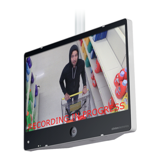
- Page 4 Alarm Input. EXAMPLE: On/Off: Message: Recording in Progress Message Position: BOTTOM Message Flash: 3 sec Message LED Control: Flashing LED Basic Setup Guide: CE-M21A-PIR / CE-M27A-PIR / CE-M32A-PIR Information in this document is subject to change without notice. 02.08.19...
- Page 5 • Check SD Card to ensure there are no hidden files or other file types on the card. • Check to ensure the image is no larger than 1024 x 768 pixels. Basic Setup Guide: CE-M21A-PIR / CE-M27A-PIR / CE-M32A-PIR Information in this document is subject to change without notice.
- Page 6 The camera image will not be displayed on the screen after a reset. Color bars will be displayed. Login to the camera and make the following adjustments to restore the camera image. Basic Setup Guide: CE-M21A-PIR / CE-M27A-PIR / CE-M32A-PIR Information in this document is subject to change without notice.
- Page 7 To mirror the image on the screen of the PVM so words are legible (not backwards), click the SYSTEM tab, then click the HDMI icon. Turn the ‘Mirror Output Image’ toggle OFF. Mirror ON Mirror OFF Basic Setup Guide: CE-M21A-PIR / CE-M27A-PIR / CE-M32A-PIR Information in this document is subject to change without notice. 02.08.19...
Need help?
Do you have a question about the CE-M21A-PIR and is the answer not in the manual?
Questions and answers