Advertisement
Quick Links
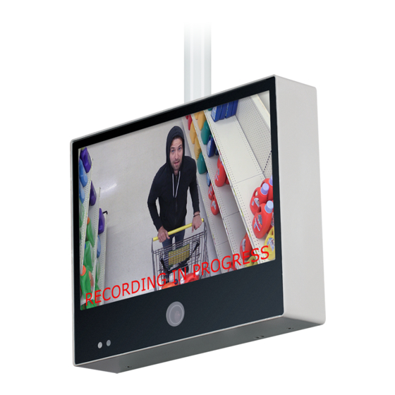
Basic Setup Guide: "A-Series" PVMs w/ Axis M3065 Camera
CE-M10A-A / CE-M21A-PIR / CE-M27A-PIR / CE-M32A-PIR / CE-M43A-PIR
Remove Cover Plate and Install PVM:
1
Remove the cover plate on the back-side of the PVM
and set aside. Install the PVM to desired VESA mounting
bracket following instructions supplied with the mount.
*Mounting Bracket Not Included, Sold Separately.
Connect DC24V Power:
2
Connect DC24V power to PVM (using the supplied
pigtail adapter cable) or AC110V (32" models only). It is
recommended that the power supply not be plugged into
the main power source during this step *Power Supply
Not Included, Sold Separately.
Connect Network:
3
Connect an ethernet cable to the port marked LAN.
To view the IP camera on the network follow the setup
instructions from the included IP camera software. This
device does not support PoE connection.
Turn Power ON:
4
After making the power and network connections, plug the power supply into a wall outlet. Connecting the
DC24V pigtail into the PVM while plugged into the main power source can cause sparking.
Camera Boot-Up:
5
Colored bars will display on the screen while the Axis IP camera is booting up. These bars will be on the screen
for approximately 20-30 seconds.
Camera Angle Adjustment:
6
If the camera appears to be slightly rotated the
angle might need to be adjusted. To adjust remove the 2
screws on the camera access door. Then turn the front of
the camera left/right until straight. Align the notch on the
front of the camera to the notch on the camera housing.
• Most E-Series PVMs are not PoE devices! Power for these units must come from 24 Volt DC power source.
Some smaller models may support PoE. Check actual power requirements prior to installation.
• 32" & 43" models: DO NOT CONNECT DC24V & AC110V POWER SIMULTANEOUSLY. Connecting both will
cause damage to the device.
Basic Setup Guide: "A-Series" PVMs w/ AXIS 3065 Camera
11.21.22
24V POWE R SUP PLY REQU IRED . S OLD S EPARATE LY
DC24V
DC24V
LAN
ANALOG
OUTPUT
Camera Access Door
Front Notch
Housing Notch
Information in this document is subject to change without notice.
1
Ethernet
HDMI
ALARM
POWER
AUTO
UP
DOWN
MENU
VESA Mounting Holes
Align 2 Notches
Advertisement

Subscribe to Our Youtube Channel
Related Manuals for Clinton Electronics CE-M10A-A


Summary of Contents for Clinton Electronics CE-M10A-A
- Page 1 Basic Setup Guide: “A-Series” PVMs w/ Axis M3065 Camera CE-M10A-A / CE-M21A-PIR / CE-M27A-PIR / CE-M32A-PIR / CE-M43A-PIR 24V POWE R SUP PLY REQU IRED . S OLD S EPARATE LY Remove Cover Plate and Install PVM: DC24V Ethernet Remove the cover plate on the back-side of the PVM and set aside.
- Page 2 DISPLAY – Image Modes Press the ‘MENU’ button on the included remote or the buttons located on the back of the PVM to adjust menu settings. Navigate up/down through the menu, press Enter to select an option and left/right to make adjustments. Press the Exit button to escape from a menu option and to exit the OSD menu.
- Page 3 “Return to Cashier” message will fl ash on the screen. “Return to Cashier” message will fl ash on the screen. SD CARD • CE-M10A-A does not include SD Card Player! • Image Mode options & names vary by model. Basic Setup Guide: “A-Series” PVMs w/ AXIS 3065 Camera Information in this document is subject to change without notice.
- Page 4 SYSTEM SETTINGS/Special Control – Message & LED Control Press the ‘MENU’ button on the included remote or the buttons located on the back of the PVM to adjust menu settings. Navigate up/down through the menu, press Enter to select an option and left/right to make adjustments. Press the Exit button to escape from a menu option and to exit the OSD menu.
- Page 5 PNG file. Save the image to the SD Card (ensure no other content is on the SD Card) • CE-M10A-A does not include SD Card Player! • The SD Card & player can be damaged if the SD Card is inserted incorrectly.
- Page 6 Resetting the AXIS M3065 Camera 10” models Reset to factory default should be used with caution. A reset to factory default will reset all camera settings, including the IP address, to the factory default values. Remove 2 screws on back of PVM Press/Hold Control Button (Slightly behind cover plate) Disconnect power from the PVM.
- Page 7 Resetting the AXIS M3065 Camera 21”~43” models Reset to factory default should be used with caution. A reset to factory default will reset all camera settings, including the IP address, to the factory default values. TOP of PVM microSD Remove 2 screws camera on bottom of PVM Press/Hold Button...
- Page 8 M3065 Camera Troubleshooting *2020+ Web UI (Axis Web ver C) ATTENTION: Updating the fi rmware may result in loss of the camera image on the PVM. Follow the steps below to re-enable the camera image. If the updated fi rmware shows with the menu bar on the left side of the page: After logging into the camera, click the System menu option.
- Page 9 M3065 Camera Troubleshooting *2017~2020 Web UI (Axis Web ver B) If the updated fi rmware shows with the menu bar on the bottom of the page: Set the Capture Mode to 1080p (HDMI) from the drop-down menu. Click the NEXT button in the lower corner, then YES to confi...
Need help?
Do you have a question about the CE-M10A-A and is the answer not in the manual?
Questions and answers