Table of Contents
Advertisement
Quick Links
®
AVR
ATmegaICE User Guide
The ATmegaICE is a real time In-Circuit Emulator (ICE) for all ATmega devices. It can
be upgraded to support future ATmega parts. It is controlled by AVR
professional front-end for both high-level and assembly level debugging. AVR Studio is
described in Section 1 in the Development Tools User Guide and must be studied care-
fully in order to take full advantage of this product.
The ATmega ICE system consists of the following elements:
AVR ICE unit
POD card ATmegaPOD
Pod cable
ATmega103/ATmega603 probe with TQFP64 adapter including cables
RS-232 cable
Power supply unit
Documentation
Section 1
Introduction
®
Studio, which is a
Rev. 1077A–01/99
1-1
Advertisement
Table of Contents

Related Manuals for Atmel AVR ATmegaICE


Summary of Contents for Atmel AVR ATmegaICE
- Page 1 Section 1 Introduction The ATmegaICE is a real time In-Circuit Emulator (ICE) for all ATmega devices. It can ® be upgraded to support future ATmega parts. It is controlled by AVR Studio, which is a professional front-end for both high-level and assembly level debugging. AVR Studio is described in Section 1 in the Development Tools User Guide and must be studied care- fully in order to take full advantage of this product.
- Page 2 Figure 1-1. ATmegaICE with Pod Connected The AVR ICE unit is the main part of the AVR ATmegaICE system. AVR Studio, which runs on a host PC, controls the ICE unit. The ICE unit must be connected to an available RS-232 port on the host PC with the supplied RS-232 cable.
- Page 3 Introduction Figure 1-4. ATmega103/ATmega603 Probe ® ATmegaICE User Guide...
- Page 4 Introduction ® ATmegaICE User Guide...
- Page 5 Section 2 Preparing the ATmegaICE System for Use Complete the following procedure in order to start using the ATmegaICE. Before connecting the probe cable to the user application: 1. Connect the pod card to the AVR ICE unit with the pod cables. Do not disassem- ble the pod cables.
- Page 6 Preparing the ATmegaICE System for Use ® ATmegaICE User Guide...
- Page 7 Section 3 ATmegaPOD ATmegaPOD is the pod card used for the microcontrollers ATmega103/603. The pod contains several jumpers which must be set to achieve the desired operation. The jumpers involved in the configuration are indicated in Figure 3-1. Figure 3-1. Pod Jumper Placements J110/J111 J500 IN-SYSTEM...
- Page 8 ATmegaPOD Voltage If the target system uses its own power supply, the output voltage must be set to the voltage in the target system. The jumpers J200-J202 are used for this purpose. The Regulation for interpretation of the different settings of these jumpers is shown in Figure 3-2. Port Pins Figure 3-2.
- Page 9 ATmegaPOD As noted above, the selected frequency range may not correspond to the crystal fre- quency due to load capacitors and/or stray capacitors. Due to long probe leads, it may be difficult to emulate the 32 kHz oscillator in many designs.
- Page 10 ATmegaPOD ® ATmegaICE User Guide...
-
Page 11: Connecting To The System
Section 4 Connecting to the System The device’s pins are placed on the four in-system connectors, J110, J111, J112 and J113. The pinout of these connectors is shown in Tables 4-1, 4-2, 4-3 and 4-4. The col- umn “#” shows the pin number on each header. The column “&” shows the correspond- ing pin number on an ATmega103/ATmega603 device. - Page 12 Connecting to the System Table 4-2. Pinout for Header J111 J111 & & TOSC2 PB7 (OC2/PWM2) RESET TOSC1 XTAL1 XTAL2 INT1 INT0 INT3 INT2 PD4 (IC1) PD7 (T2) PD6 (T1) Table 4-3. Pinout for Header J112 J112 & & PC1 (A9) PC0 (A8) PC3 (A11) PC2 (A10)
- Page 13 Connecting to the System Table 4-4. Pinout for Header J113 J113 & & PA1 (AD1) PA2 (AD2) PA0 (AD0) PF7 (ADC7) PF5 (ADC5) PF6 (ADC6) PF3 (ADC3) PF4 (ADC4) PF1 (ADC1) PF2 (ADC2) AREF PF0 (ADC0) AVCC AGND Figure 4-1. Pin Numbering J110 J111 15 13 11...
- Page 14 Connecting to the System ® ATmegaICE User Guide...
-
Page 15: Trace Buffer
Section 5 Trace Buffer The AVR ATmegaICE has a 32K x 96-bit trace buffer which stores information about program execution for every clock cycle. When the emulator is stopped, this trace buffer can be examined to extract information about the history of the emulated program. The details on which data are stored and how to retrieve them are described in the AVR Stu- dio User Guide. - Page 16 Trace Buffer ® ATmegaICE User Guide...
-
Page 17: External Triggers
Section 6 External Triggers The AVR ATmegaICE has five external trigger inputs and five trigger outputs, all located on the AUX connector next to the pod connector. The trigger inputs can act as break signals to the emulator, and/or they can be logged in the trace buffer. - Page 18 External Triggers ® ATmegaICE User Guide...
-
Page 19: Troubleshooting Procedures
Turn off power and disconnect your pod card. Then try again. If everything is OK now, this indicates that your settings on the pod card are wrong and disturbs normal operation. If your ATmegaICE system still operates abnormally, please contact your nearest Atmel sales office or AVR support at avr@atmel.com. ®... - Page 20 Troubleshooting Procedures ® ATmegaICE User Guide...
-
Page 21: Connector Description
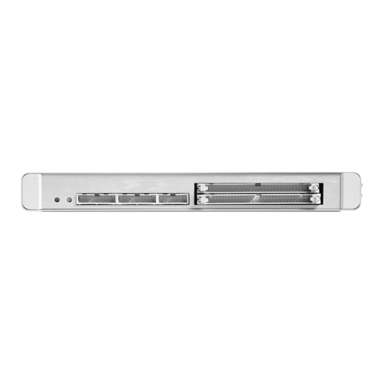
Section 8 AVR ATmegaICE Connector Description Logic Analyzer 1 Figure 8-1. Logic Analyzer 1 Connector Connector Description The connector marked “Logic Analyzer 1” on the back panel of the AVR ICE unit has the following pin-out with signals from the instruction address bus. - Page 22 AVR ATmegaICE Connector Description Logic Analyzer 2 Figure 8-2. Logic Analyzer 2 Connector Connector Description The connector marked “Logic Analyzer 2” on the back panel of the AVR ICE unit has the following pin-out with signals from the instruction data bus.
-
Page 23: Technical Specifications
Section 9 Technical Specifications System Unit Physical Dimensions ..(H x W x D) 32.4 x 277.1 x 218.6 mm / 1.3 x 10.8 x 8.5 in Weight ........... . 400g / 0.88 lbs Power Voltage Requirements . - Page 24 Technical Specifications Internal Watchdog RC oscillator: Running frequency ......... 1.0 MHz ± 30% Operation Minimum running speed .
- Page 25 Buyer the purchase price of such goods. No goods may be returned to Atmel without Atmel’s Returned Material Authorization form. Prior to any return of goods by Buyer pursuant to this Section, Buyer shall afford Atmel the opportunity to inspect such goods at Buyer’s location, and any such goods so inspected shall not be returned to Atmel without its prior written consent.
- Page 26 Buyer or any third parties for consequential, incidental, indi- Liability rect, exemplary, special, or other damages. Atmel’s total liability shall not exceed the total amount paid by Buyer to Atmel hereunder. Atmel shall not under any circum- stances be liable for excess costs of reprocurement. ®...
- Page 27 No licenses to patents or other intellectual prop- er ty of Atmel are granted by the Company in connection with the sale of Atmel products, expressly or by implication. Atmel’s products are not authorized for use as critical components in life suppor t devices or systems.
Need help?
Do you have a question about the AVR ATmegaICE and is the answer not in the manual?
Questions and answers