Advertisement
Quick Links
AT90ICEPRO User Guide
Downloaded from
Elcodis.com
electronic components distributor
The AT90ICEPRO is a real time In-Circuit Emulator (ICE) for all AT90S1200, -S2313,
-S2323, -S2333, -S2343, -S4414, -S4433, -S4434, -S8515 and -S8535 devices. It can
be upgraded to support future AVR
fessional front-end for both high-level and assembly level debugging. AVR Studio is
described in Section 1 in the Development Tools User Guide and must be studied care-
fully in order to take full advantage of this product.
The AVR AT90ICEPRO ICE system consist of the following elements:
AVR ICE Unit
Pod card AT90ADCPOD
Pod Cable
AT90S1200/-2313 probe with cable (DIL20)
AT90S4414/-8515/-4434/-8535 probe with cable (DIL40)
AT90S2323/-2343 probe with cable (DIL8)
AT90S2333/-4433 probe with cable (DIL28)
A RS-232 cable
A Power Supply unit
Documentation
Introduction
®
parts. It is controlled by AVR Studio, which is a pro-
Section 1
1-1
Rev. 1024B–01/99
Advertisement

Related Manuals for Atmel AT90ICEPRO


Summary of Contents for Atmel AT90ICEPRO
- Page 1 Section 1 Introduction The AT90ICEPRO is a real time In-Circuit Emulator (ICE) for all AT90S1200, -S2313, -S2323, -S2333, -S2343, -S4414, -S4433, -S4434, -S8515 and -S8535 devices. It can ® be upgraded to support future AVR parts. It is controlled by AVR Studio, which is a pro- fessional front-end for both high-level and assembly level debugging.
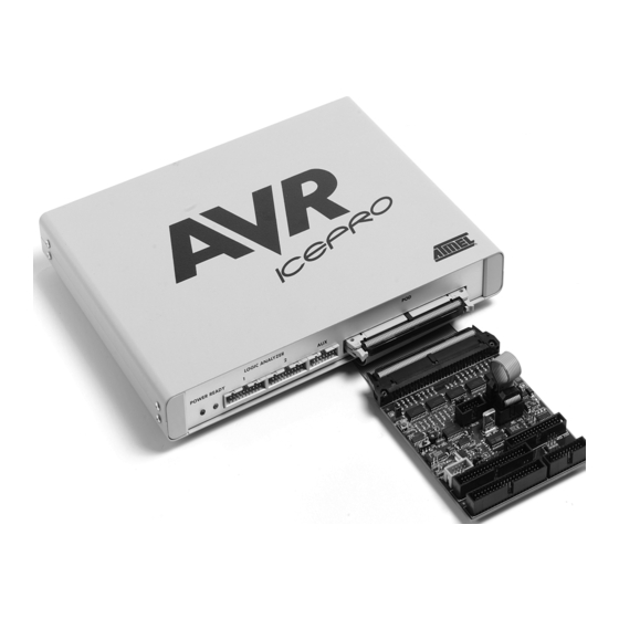
- Page 2 Figure 1-1. AVR AT90ICEPRO with AT90ADCPOD The AVR ICE unit is the main part of the AVR AT90ICEPRO system. AVR Studio, which runs on a host PC, controls the ICE unit. The AVR ICE unit must be connected to an available RS-232 port on the host PC with the supplied RS-232 cable.
- Page 3 It is extremely important that the probe cable is correctly connected to the user application. The colored wire of the probe cable indicates pin 1 of the AVR device. Figure 1-3. AVR ICEPRO Front Panel Figure 1-4. AVR ICEPRO Back Panel AT90ICEPRO User Guide Downloaded from Elcodis.com electronic components distributor...
- Page 4 Introduction AT90ICEPRO User Guide Downloaded from Elcodis.com electronic components distributor...
- Page 5 Section 4. When all jumpers are set correctly, turn on the power. When the green LED is lit, the AVR AT90ICEPRO system is ready for use. Start AVR Studio, and begin your AVR emulation session. AT90ICEPRO User Guide Downloaded from Elcodis.com...
- Page 6 AT90ICEPRO User Guide Downloaded from Elcodis.com electronic components distributor...
- Page 7 Emulator Options. On the pod card, make sure to use the appropriate probe cable (20 pins for 20 pin device and so on) and connect your application to the connector labeled with the correct part number. Please note that it may damage your AT90ICEPRO if you plug the probe cable into the wrong connector.
- Page 8 AT90ICEPRO User Guide Downloaded from Elcodis.com electronic components distributor...
-
Page 9: Power System
5V. The AVR ICE itself uses about 10W, so if the user application is powered from the AVR AT90ICEPRO system, it can not use more then 5 W (i.e. 5V/1A). If this value is exceeded, the AVR AT90ICEPRO system may be damaged or not work prop- erly. - Page 10 The AVR AT90ICEPRO Power System AT90ICEPRO User Guide Downloaded from Elcodis.com electronic components distributor...
- Page 11 Section 5 The AVR AT90ICEPRO Clock System The AVR AT90ICEPRO system can use one out of three available clock sources; the programmable internal clock in the ICEPRO, a crystal or an external oscillator in the user application. The internal clock can be adjusted between 400 kHz and 20 MHz. Any frequency within this range can be selected, and will be produced with an accuracy better than 200 PPM for most frequencies.
- Page 12 The AVR AT90ICEPRO Clock System AT90ICEPRO User Guide Downloaded from Elcodis.com electronic components distributor...
- Page 13 Section 6 The AVR AT90ICEPRO Reset System The AVR AT90ICEPRO system has two independent reset systems. One is for the AVR AT90ICEPRO system itself, and the other is for the emulated AVR device. The ICE reset button is placed on the back panel of the box. The button is labeled “ICE RESET”, and is hidden in the back panel for safety reasons.
- Page 14 The AVR AT90ICEPRO Reset System AT90ICEPRO User Guide Downloaded from Elcodis.com electronic components distributor...
- Page 15 If an external oscillator out- put is used as the clock source of the Timer oscillator, mount a jumper on connector J104. AT90ICEPRO User Guide Downloaded from Elcodis.com electronic components distributor...
- Page 16 The Timer Oscillator AT90ICEPRO User Guide Downloaded from Elcodis.com electronic components distributor...
- Page 17 The jumpers on connectors J105 and J106, labeled S0 and S1, must be set correctly to make the analog comparator work properly. Figure 8-1. Jumpers J105 and J106 Target VCC S1/J105 S0/J106 S1200, S2313 S4414, S4434, S8515, S8535 S2333, S4433 AT90ICEPRO User Guide Downloaded from Elcodis.com electronic components distributor...
- Page 18 AT90ICEPRO User Guide Downloaded from Elcodis.com electronic components distributor...
- Page 19 The connectors not described in this document are intended for future use. The connec- tor labeled RST\ must have it’s jumper placed in position ON. The 6-pin header connec- tor is intended for possible upgrades of the SW on your pod card. AT90ICEPRO User Guide Downloaded from Elcodis.com...
- Page 20 Connectors not Described in this Document AT90ICEPRO User Guide Downloaded from Elcodis.com electronic components distributor...
-
Page 21: Trace Buffer
Section 10 Trace Buffer The AVR AT90ICEPRO has a 32K x 96-bit trace buffer which stores information about program execution for every clock cycle. When the emulator is stopped, this trace buffer can be examined to extract information about the history of the emulated program. The details on which data are stored and how to retrieve them are described in the AVR Stu- dio User Guide. - Page 22 10-2 AT90ICEPRO User Guide Downloaded from Elcodis.com electronic components distributor...
-
Page 23: External Triggers
Section 11 External Triggers The AVR AT90ICEPRO has five external trigger inputs and five trigger outputs, all located on the AUX connector next to the pod connector. The trigger inputs can act as break signals to the emulator, and/or they can be logged in the trace buffer. - Page 24 External Triggers the trace logic is clocked on the AVR clock. The emulator may break on a glitch signal which is too narrow to be traced. 11-2 AT90ICEPRO User Guide Downloaded from Elcodis.com electronic components distributor...
-
Page 25: Troubleshooting Procedures
Section 12 Troubleshooting Procedures If the AVR AT90ICEPRO system starts to behave unpredictably, try one of the following: Push the Stop button in AVR Studio, then the reset button, and then try again. Push the “ICE RESET” button on the back panel and restart AVR Studio. - Page 26 Troubleshooting Procedures 12-2 AT90ICEPRO User Guide Downloaded from Elcodis.com electronic components distributor...
- Page 27 Section 13 AVR AT90ICEPRO Connector Description Figure 13-1. Logic Analyzer 1 Connector 13.1 Logic Analyzer 1 The connector marked “Logic Analyzer 1” on the back panel of the AVR ICE unit has the following pin-out with signals from the instruction pre-fetch bus:...
- Page 28 AVR AT90ICEPRO Connector Description 13.2 Logic Analyzer 2 Figure 13-2. Logic Analyzer 2 Connector Connector Description The connector marked “Logic Analyzer 2” on the back panel of the AVR ICE unit has the following pin-out with signals from the instruction pre-fetch bus: Table 13-2.
- Page 29 AVR AT90ICEPRO Connector Description 13.3 AUX Connector Figure 13-3. AUX Connector Description The connector marked “AUX” on the back panel of the AVR ICE unit is used for external triggers and has the following pin-out. Table 13-3. Pin-Out AUX Connection...
- Page 30 AVR AT90ICEPRO Connector Description 13-4 AT90ICEPRO User Guide Downloaded from Elcodis.com electronic components distributor...
-
Page 31: Technical Specifications
Maximum frequency ..........20.0 MHz External Crystal AT90ICEPRO User Guide 14-1 Downloaded from Elcodis.com... - Page 32 Permanent Pull-up..........1.0 MΩ 14-2 AT90ICEPRO User Guide Downloaded from Elcodis.com...
- Page 33 Buyer the purchase price of such goods. No goods may be returned to Atmel without Atmel’s Returned Material Authorization form. Prior to any return of goods by Buyer pursuant to this Section, Buyer shall afford Atmel the opportunity to inspect such goods at Buyer’s location, and any such goods so inspected shall not be returned to Atmel without its prior written consent.
- Page 34 Buyer or any third parties for consequential, incidental, indi- Liability rect, exemplary, special, or other damages. Atmel’s total liability shall not exceed the total amount paid by Buyer to Atmel hereunder. Atmel shall not under any circum- stances be liable for excess costs of reprocurement. 15-2...
- Page 35 No licenses to patents or other intellectual prop- er ty of Atmel are granted by the Company in connection with the sale of Atmel products, expressly or by implication. Atmel’s products are not authorized for use as critical components in life suppor t devices or systems.
Need help?
Do you have a question about the AT90ICEPRO and is the answer not in the manual?
Questions and answers