Table of Contents
Advertisement
Quick Links
SERVICE MANUAL
EN
Model: 81465 RFXi
IMPORTANT: Before using this equipment, carefully read SAFETY PRECAUTIONS and all
instructions in this manual. Keep this Service Manual for future reference.
AH-17-02-R1 (10/2019)
RansFlex Applicators for In-Direct
Charge Waterbased Applicators
1 / 55
www.carlisleft.com
Advertisement
Table of Contents

Related Manuals for Carlisle Ransburg RansFlex RFXi Series


Summary of Contents for Carlisle Ransburg RansFlex RFXi Series
- Page 1 SERVICE MANUAL RansFlex Applicators for In-Direct Charge Waterbased Applicators Model: 81465 RFXi IMPORTANT: Before using this equipment, carefully read SAFETY PRECAUTIONS and all instructions in this manual. Keep this Service Manual for future reference. AH-17-02-R1 (10/2019) 1 / 55 www.carlisleft.com...
- Page 2 MANUAL CHANGES NOTE: This manual has been changed from revision AH-17-02-R0 to revision AH-17-02-R1. Reasons for this change are noted under “Manual Change Summary” inside the back cover of this manual. AH-17-02-R1 (10/2019) 2 / 55 www.carlisleft.com...
-
Page 3: Table Of Contents
CONTENTS CONTENTS SAFETY: Safety Precautions ..............................4 Hazards / Safegaurds ............................5 ATEX/FM REQUIREMENTS: 9-12 Ransflex RFXi - Waterbase Only .........................10 Available Accessories ............................11 INTRODUCTION: 13-16 General Description .............................13 Ransflex New Features ............................13 Specifications 81465 Ransflex Indirect Charge Waterbase ................14 Typical Installation ...............................16 INSTALLATION: 17-19 81465 Ransflex Indirect Charge Waterborne Installation ..................17... -
Page 4: Safety
This information relates to USER SAFETY and safety literature for your equipment, contact your local and PREVENTING EQUIPMENT PROBLEMS. To help you Carlisle Fluid Technologies representative or Carlisle Fluid recognize this information, we use the following symbols. Technologies technical support. -
Page 5: Hazards / Safegaurds
SAFETY AREA SAFEGUARDS HAZARD Tells where hazards Tells how to avoid the hazard. Tells what the hazard is. may occur. Fire Hazard Spray Area Fire extinguishing equipment must be present in the Improper or inadequate spray area and tested periodically. operation and maintenance procedures will cause a fire Spray areas must be kept clean to prevent the... - Page 6 SAFETY AREA SAFEGUARDS HAZARD Tells where hazards Tells how to avoid the hazard. Tells what the hazard is. may occur. Explosion Hazard Spray Area Improper or inadequate Electrostatic arcing must be prevented. Safe sparking operation and maintenance distance must be maintained between the parts being procedures will cause a coated and the applicator.
- Page 7 SAFETY AREA SAFEGUARDS HAZARD Tells where hazards Tells how to avoid the hazard. Tells what the hazard is. may occur. Spray Area / Electrical Discharge High Voltage There is a high voltage device Parts being sprayed and operators in the spray Equipment that can induce an electrical area must be properly grounded.
- Page 8 SAFETY AREA SAFEGUARDS HAZARD Tells where hazards Tells how to avoid the hazard. Tells what the hazard is. may occur. Electrical Discharge Electrical Unless specifically approved for use in hazardous Equipment locations, the power supply, control cabinet, and all High voltage equipment is utilized in the process.
-
Page 9: Atex/Fm Requirements
ATEX ATEX REQUIREMENTS Atex Requirements be zoned around the applicator. No ATEX approval is required. It is the end users responsibility to insure all of This product provides an indirect charge to water based these conditions are met. materials that will improve the transfer efficiency over non-electrostatic products. -
Page 10: Ransflex Rfxi - Waterbase Only
ATEX RANSFLEX RFXi - WATERBASE ONLY 81465 - ABCDEF Base Optional Model No. Designations (Ordering Information Only) CONFIGURATION DWG. 81466-00 REV. A AH-17-02-R1 (10/2019) 10 / 55 www.carlisleft.com... -
Page 11: Available Accessories
ATEX “R” (Air Cap) “S” (Fluid Nozzle) “T” (Pressure Reducer) ATOMIZATION - TABLE OF “A” DASHES “S” “T” “A” Dash No. “A” Description “R” T SERIES 1.2mm 80383-00 80239-12 74963-05 T SERIES 1.4mm 80383-00 80239-14 74963-05 T SERIES 1.8mm 80383-00 80239-18 74963-05 T SERIES 1.0mm... - Page 12 ATEX “W” 80269-45 FLUID INLET - TABLE OF “D” DASHES “D” Dash No. “D” Description “W” STD FLUID INLET TUBE 80269-45 FLUID HOSE - TABLE OF “E” DASHES “X” “E” Dash No. “E” Description NO FLUID HOSE FLUID HOSE, 10m 80303-10 FLUID HOSE, 15m 80303-15...
-
Page 13: Introduction
INTRODUCTION INTRODUCTION GENERAL DESCRIPTION RANSFLEX NEW FEATURES The Ransflex is an air atomizing applicator powered only • Light weight and easy to maneuver. by a pressurized air source. Pressurized air creates rotation • Ergonomic handle design to reduce of a turbine generator that powers a cascade. The cascade operator fatigue. -
Page 14: Specifications 81465 Ransflex Indirect Charge Waterbase
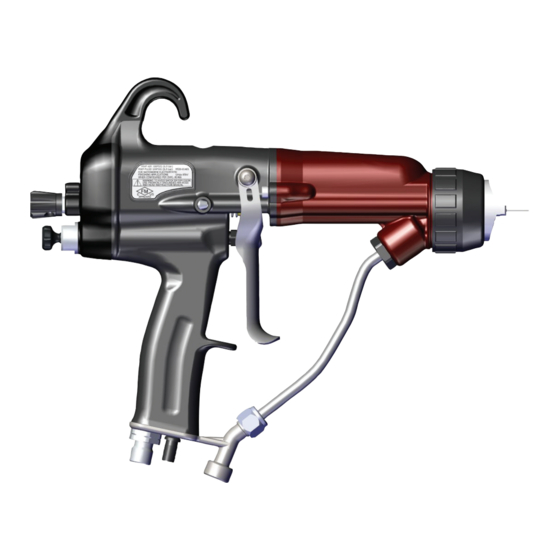
INTRODUCTION SPECIFICATIONS: 81465 RANSFLEX INDIRECT CHARGE WATERBASE Environmental/Physical Applicator Length: 254mm (10-inches) Weight: (Without Hose) 600 grams (21.3 oz.) Hose 80558-XX Lengths (Std): 5m, 10m, 15m and 20m Electrical Operating Voltage: 65kV DC (-) maximum Current Output: 120 microamperes maximum Paint Resistance:* Waterbase paint only with grounded source Part Sprayability:... - Page 15 INTRODUCTION Figure 1: Ransflex Indirect Charge Waterborne Electrostatic Spray Applicator 81465 RANSFLEX INDIRECT CHARGE WATERBORNE ELECTROSTATIC SPRAY APPLICATOR 81465 Description Description Needle/Electrode Exhaust Air Hose Barrel Fluid Hose Handle Voltage On/Off Switch Fan Adjustment Trigger Fluid Adjustment Compensation Valve Air Hose Air Cap with Charging Electrodes / Fluid Nozzle AH-17-02-R1 (10/2019) 15 / 55...
-
Page 16: Typical Installation
INTRODUCTION Figure 2: Ransflex Installation for Waterbase Materials RANSFLEX INDIRECT CHARGE WATERBASE TYPICAL INSTALLATION Description Description Ransflex 81465 Fluid Supply (Grounded) Ball Valve Fluid Regulator Air Regulator with Pressure Gauge Air Hose (80558-XX) Air Hose Ground Wire Air / Water Separator Main Air Supply Line Fluid Line AH-17-02-R1 (10/2019) -
Page 17: Installation
INSTALLATION INSTALLATION Air Hose WA R N I N G WA R N I N G † For proper safe function of the applicator, the † The user MUST read and be familiar with the 80558-XX Air Hose Assembly must be used (either "Safety"... -
Page 18: Installation
INSTALLATION 2. All objects inside spray area must be grounded - refer- ence EN 50176 and/or NFPA-33. Resistance to earth ground must be less than 1 meg Ohm. 3. Flammable liquids must be contained in approved metalic grounded containers. 2. Turn off power. Interlocks Required Interlock the solvent supply with the main supply air to the applicator. - Page 19 INSTALLATION 4. Connect air. OR... 5. Trigger applicator with fluid off. Look for leaks in any connections 6. Activate fluid, check for leaks with solvent flush if required. AH-17-02-R1 (10/2019) 19 / 55 www.carlisleft.com...
-
Page 20: Operation
OPERATION OPERATION APPLICATOR OPERATION 3. Activate trigger to start material stream into grounded metal bucket or suitable area. 1. Set fluid pressure using flow regulator. WA R N I N G † The bucket or area sprayed into must be grounded to true earth ground. - Page 21 OPERATION 5. Re-connect air supply. 10. Turn on voltage and trigger applicator. Green light should be on. OR... 11. Adjust fluid pressure and air pressure as required to achieve finish. 12. Adjust air cap position as required. Adjust air pressure. Position air cap to achieve pattern direction.
- Page 22 OPERATION 13. Adjust fan pattern as required. 15. Adjust compensation valve with small driver. NOTE † The compensation valve adjustment is used to adjust fan and atomization pressure at the same time when the pressure to run the turbine is higher than the 14.
-
Page 23: Flushing / Color Change Procedure
OPERATION FLUSHING / COLOR 3. Discharge fluid into appropriate earth grounded CHANGE PROCEDURE metal container 1. Turn off electrostatics. WA R N I N G † The solvent supply must be interlocked with the applicator supply air. 2. Disconnect air to applicator. 4. -
Page 24: New Nozzle Design
OPERATION NEW NOZZLE DESIGN With the release of the Ransflex applicator a new configuration of nozzles was also released. Red nozzles 1.2 mm I.D. Grey nozzles 1.4 mm I.D. Green nozzles 1.8 mm I.D. Air cap to be Air cap part used with nozzle. -
Page 25: Maintenance
MAINTENANCE MAINTENANCE SUITABLE SOLVENTS FOR WA R N I N G CLEANING RANSFLEX APPLICATORS † The user MUST read and be familiar with the safety instructions in this manual. When cleaning the applicator, a suitable solvent for † If compressed used cleaning, cleaning depends on the part(s) of the applicator... -
Page 26: Routine Schedule
MAINTENANCE CAUTION CAUTION † Nozzles from previous Ransburg design are not † NEVER remove the fluid nozzle assembly while compatable with the Ransflex design. Use of these paint is in the applicator or paint may enter into the nozzles could cause equipment malfunction and air passages. - Page 27 MAINTENANCE • Check that atomizer assembly is clean and undamaged. NOTE † Standard electrode is "snap back" spray wire electrode. • Straighten the applicator electrode if necessary. • Clean the fluid filter, if used. Bi-Yearly • Check air hose resistance. If resistance is greater than .5 MW the hose should be replaced.
- Page 28 MAINTENANCE 2. O-ring in barrel, replace as required. 2. Clean and replace as necessary. 3. Install in reverse order. 3. Install fluid nozzle using 80353-00 wrench. Tighten till nozzle seats on O-ring and then 1/8 additional turn. Fluid Nozzle Removal WA R N I N G †...
- Page 29 MAINTENANCE 2. Remove fluid tube. 2. Carefully disconnect harness by pulling connector on both sides by hand and rocking it side to side to remove. 3. Pull barrel away. 3. Replace cascade as necessary. 4. Apply LSCH 0009 grease to end of cascade. Remove/Replace Cascade 1.
- Page 30 MAINTENANCE Packing Removal/Replace 5. Remove all parts, clean with non-polar solvent. Inspect for any discolored areas. Replace parts as required. 1. Remove barrel from handle. 2. Use 80353 wrench to remove nut. 6. Prior to installation apply dielectric grease inside packing tube, completely full.
- Page 31 MAINTENANCE 13. Tighten jam nuts. 10. Install Bellville washers in sequence shown. Re-Install Needle Shaft Into Barrel 1. Install needle shaft into barrel with die-electric grease. 11. Install rear nut. Install jam nuts finger tight. 2. Tighten packing using wrench. Pull back and forth on the needle shaft till a slight amount of drag is felt.
- Page 32 MAINTENANCE 4. Re-install trigger. NOTE NOTE † The gasket between the handle and barrel is reuse- able. It should not be replaced unless torn or damaged. Re-Install Barrel 1. Install barrel over cascade. Rear Cover/Motor Module Repair 1. Loosen cover screw with 3mm driver. 2.
- Page 33 MAINTENANCE Remove motor assembly by pulling out on 3 arms, pull motor out. 4. Remove porting block. 4. Disconnect motor connector from handle wire harness connector. Motor Removal 1. Remove light pipe. NOTE NOTE † Block must be pulled out with fingers rocking the part side to side while pulling.
- Page 34 MAINTENANCE 3. Install cartridge then o-ring (if removed). 6. Push on edges to remove fluid valve cartridge. Re-assembly 4. Install screw and retainer. 1. Install porting block on motor. Align screw heads into porting recess. NOTE NOTE † There is only one way to install the motor. †...
- Page 35 MAINTENANCE 9. Install fan air valve cartridge. 6. Install fluid valve cartridge. 10. Tighten cover screw. 7. Install gasket and re-connect motor connector to handle harness connector. NOTE NOTE † The gasket between the handle and rear cover is reu- seable.
- Page 36 MAINTENANCE 5. Insert air valve and spring. 3. Remove bracket, gasket and o-ring. 6. Tighten packing nut till light drag is felt on the shaft while 4. Install o-ring, gasket and bracket. moving it back and forth. 7. Install rear cover assembly. NOTE NOTE 8.
- Page 37 MAINTENANCE 6. Tighten fluid nut. 3. Remove lower fluid nut. Gun Wrench Functions 4. Air fiting. 80353-00 1. Adjust packings. 5. Remove rear cartridge. 2. Remove nozzles For V Series For C & T Series AH-17-02-R1 (10/2019) 37 / 55 www.carlisleft.com...
-
Page 38: Troubleshooting Guide
MAINTENANCE TROUBLESHOOTING GUIDE General Problem Possible Cause Solution ELECTRICAL On-Off lever in wrong position Ensure the On/Off lever is in the On position. No kV Low pressure Ensure 2.8 bar (40 psig) at the applicator handle with applicator triggered. No ground connection Ensure the air hose is properly grounded to the earth ground. -
Page 39: Parts Identification
PARTS IDENTIFICATION PARTS IDENTIFICATION RANSFLEX RFXi - INDIRECT CHARGE WATERBASE 81465 - ABCDEF Base Optional Model No. Designations * NOTE: All nozzles available in kits of 3. ATOMIZATION - TABLE OF “A” DASHES “A” Dash No. “A” Description “1” “2” “3”... - Page 40 PARTS IDENTIFICATION TRIGGER - TABLE OF “C” DASHES “5” “C” Dash No. “C” Description 2 FINGER TRIGGER 80211-00 4 FINGER TRIGGER 80386-00 2 FINGER SMALL PROFILE 80566-00 FLUID INLET - TABLE OF “D” DASHES “6” “D” Dash No. “D” Description STD FLUID INLET TUBE 80269-65 FLUID HOSE - TABLE OF “E”...
- Page 41 PARTS IDENTIFICATION RETAINING RING 80532-00 Qty. Item No. Part No. Description 80531-00 NUT, RETAINING LSOR0005-17 O-RING, ENCAPSULATED AH-17-02-R1 (10/2019) 41 / 55 www.carlisleft.com...
- Page 42 PARTS IDENTIFICATION RFXi 65kV NEEDLE SHAFT 80263-65 Qty. Item No. Part No. Description 70430-01 ASSEMBLY ELECTRODE, HIGH WEAR 80677-00 ADAPTER, MALE 14323-00 SEAL, CHEVRON, 3/8 DIA. 14323-00-K4 SEAL, CHEVRON (KIT OF 4) 18821-00 ADAPTER-FEMALE-CHEVRON 80257-65 TUBE, PACKING 80225-65 NEEDLE SHAFT ASSEMBLY 79001-06 O-RING, SOLVENT PROOF 78629-00...
-
Page 43: Items For Rfxi (65Kv) Unit
PARTS IDENTIFICATION RFXi 65kV BARREL Qty. Item No. Part No. Description 80724-00 ASSEMBLY, BARREL & O-RING 80263-65 ASSEMBLY, NEEDLE SHAFT 80242-00 NUT, REAR JAM 80243-00 NUT, FRONT JAM 80258-00 SPRING, FLUID RETURN 80250-65 ASSEMBLY, CASCADE (65 kV) BARREL AND O-RING P/N 80724-00 RFXi 65kV BARREL AND O-RING P/N 80724-00 Qty. -
Page 44: Handle Components For All Models
PARTS IDENTIFICATION HANDLE COMPONENTS FOR ALL MODELS HANDLE COMPONENTS Qty. Item No. Part No. Description 80775-00 INCLUDES HANDLE (80870-00) AND REAR COVER WITH MOTOR (80378-00) ASSEMBLY (ADJUSTABLE FLUID CONTROL) 80775-01 INCLUDES HANDLE (80870-00) AND REAR COVER WITH MOTOR (80378-00) ASSEMBLY (NON-ADJUSTABLE FLUID CONTROL) 80745-00 GASKET, BARREL EMF-201-04... - Page 45 PARTS IDENTIFICATION HANDLE WITH REAR COVER WITH MOTOR 80775-00/01 Item No. Part No. Description Qty. 80870-00 ASSEMBLY, HANDLE 80244-00 ASSEMBLY, VALVE, AIR 80533-00 SPRING, AIR VALVE 80262-00 ASSEMBLY, VALVE, ADJUSTABLE FLUID CONTROL 80262-01 ASSEMBLY, VALVE, NON-ADJUSTABLE FLUID CONTROL 80273-00 ASSEMBLY, VALVE FAN AIR 80378-00 REAR COVER AND MOTOR ASSEMBLY 80732-00...
- Page 46 PARTS IDENTIFICATION HANDLE ASSEMBLY 80870-00 Item No. Description Qty. Part No. 80870-00 ASSEMBLY, HANDLE INCLUDES ALL PARTS BELOW, MOTOR CONTROL BOARD AND HARNESSES 80274-00 SCREW, BARREL-HANDLE 80229-00 NUT, RETAINING, AIR VALVE 10051-05 CUP SEAL, SPRING LOADED REAR CARTRIDGE ASSEMBLY 80262-00 (ADJUSTABLE FLUID CONTROL) Qty.
- Page 47 PARTS IDENTIFICATION REAR CARTRIDGE ASSEMBLY 80262-01 (NON-ADJUSTABLE FLUID CONTROL) Qty. Item No. Part No. Description 80262-01 ASSEMBLY, FLUID CARTRIDGE (NON-ADJUSTABLE) 79001-08 O-RING, SOLVENT PROOF 80273-00 FAN AIR CARTRIDGE Qty. Item No. Part No. Description 80273-00 ASS’Y., FAN VALVE (INCLUDES ALL PARTS BELOW) 79001-16 O-RING, SOLVENT PROOF AH-17-02-R1 (10/2019)
- Page 48 PARTS IDENTIFICATION 80378-00 REAR COVER WITH MOTOR ASSEMBLY Item No. Part No. Description Qty. 80378-00 COVER, REAR ASSEMBLY (INCLUDES ALL PARTS BELOW) 80213-00 PIPE, LIGHT 80255-00 ASSEMBLY, MOTOR 79775-00 BLOCK, PORTING 7554-61 O-RING, SOLVENT RESISTANT 80275-00 SCREW 80219-00 BRACKET, LOCKING AH-17-02-R1 (10/2019) 48 / 55 www.carlisleft.com...
- Page 49 PARTS IDENTIFICATION 80255-00 MOTOR ASSEMBLY Item No. Part No. Description Qty. 80255-00 ASSEMBLY, MOTOR (INCLUDES ALL PARTS BELOW) 80217-00 COVER SUPPORT, MOTOR 79796-00 SCREW, MOTOR * NOTE: All nozzles available in kits of 3. AH-17-02-R1 (10/2019) 49 / 55 www.carlisleft.com...
- Page 50 PARTS IDENTIFICATION 80254-00 REAR COVER ASSEMBLY Qty. Item No. Part No. Description 80254-00 COVER, REAR (CONTAINS PARTS BELOW) 80274-00 M4 X .7 SHCS * Available after August 1, 2015 AH-17-02-R1 (10/2019) 50 / 55 www.carlisleft.com...
-
Page 51: Accessories
PARTS IDENTIFICATION 79862-02 3mm Hex Driver LSCH 0009 Grease 80353-00 Gun Wrench 80395-00 ACCESSORIES INCLUDED WITH RFXi Part No. Description 27141-081 Wrap, Spiral 59972-00 Pack of 4 LSCH0009 Grease 76102-00 Applicator Mounting Bracket 76652-01 HV Probe 76652-02 Spayability and SCI Paint Test Meter 76652-03 Paint Resistivity, Sprayability 76652-04... -
Page 52: Spare Parts Kits
PARTS IDENTIFICATION SPARE PARTS KITS Description Part No. 79001-07-K3 Fluid inlet o-ring of barrels 80264-XX-K3 V Series nozzles in kits of 3 (XX = 12, 14 or 18) 80464-XX-K3 V Series high wear nozzles in kits of 3 (XX = 14, 18) 80230-XX-K3 C Series nozzles in kits of 3 (XX = 12, 14 or 18) 80239-XX-K3... -
Page 53: Recommended Spare Parts
PARTS IDENTIFICATION RANSFLEX RECOMMENDED SPARE PARTS (Quantities Per Applicator) Part # Description 80239-XX Nozzle, Fluid T Series 80239-XX-K3 Nozzle, Fluid T Series (Kit of 3) 80724-00 Assembly, Barrel (RFXi Models) (with Front Seal) 80250-65 Cascade Assembly (RFXi Models) 80745-00 Gasket, Barrel 80383-00 Air Cap T Series 80532-00... -
Page 54: Manual Change Summary
MANUAL CHANGES MANUAL CHANGE SUMMARY AH-17-02-R1 - Replaces AH-17-02-R0 with the folowing changes: Change Description Page(s) Update to current design Add MANUAL CHANGE SUMMARY pages 2, 53 Update SAFETY section Change labels from 0518 to 2813 AH-17-02-R1 (10/2019) 54 / 55 www.carlisleft.com... - Page 55 This product is covered by Carlisle Fluid Technologies materials and workmanship limited warranty. The use of any parts or accessories, from a source other than Carlisle Fluid Technologies, will void all warranties. For specific warranty information please contact Carlisle Fluid Technologies.
Need help?
Do you have a question about the Ransburg RansFlex RFXi Series and is the answer not in the manual?
Questions and answers