Chapters
Table of Contents

Related Manuals for Stahl 9440/22 Series


Summary of Contents for Stahl 9440/22 Series
- Page 1 Betriebsanleitung Additional languages www.r-stahl.com CPU & Power Modul für Zone 1 / Div. 1 Reihe 9440/22, 9490...
-
Page 2: Table Of Contents
Inhaltsverzeichnis Allgemeine Angaben ...................3 Hersteller ......................3 Angaben zur Betriebsanleitung ................3 Weitere Dokumente ....................3 Konformität zu Normen und Bestimmungen ............3 Erläuterung der Symbole ..................4 Symbole in der Betriebsanleitung ...............4 Warnhinweise .....................4 Symbole am Gerät ....................5 Sicherheitshinweise ....................5 Aufbewahrung der Betriebsanleitung ..............5 Qualifikation des Personals ................5 Sichere Verwendung ...................6 Umbauten und Änderungen ................7... -
Page 3: De De
2018-08-13·BA00·III·de·06 Die Originalbetriebsanleitung ist die englische Ausgabe. Diese ist rechtsverbindlich in allen juristischen Angelegenheiten. Weitere Dokumente • Kopplungsbeschreibung IS1 (Download unter www.r-stahl.com) • Datenblatt Dokumente in weiteren Sprachen, siehe www.r-stahl.com. Konformität zu Normen und Bestimmungen Zertifikate und EU-Konformitätserklärung, siehe www.r-stahl.com. -
Page 4: Erläuterung Der Symbole
Erläuterung der Symbole Erläuterung der Symbole Symbole in der Betriebsanleitung Symbol Bedeutung Tipps und Empfehlungen zum Gebrauch des Geräts Gefahr durch explosionsfähige Atmosphäre Gefahr durch spannungsführende Teile Warnhinweise Warnhinweise unbedingt befolgen, um das konstruktive und durch den Betrieb bedingte Risiko zu minimieren. Die Warnhinweise sind wie folgt aufgebaut: •... -
Page 5: Symbole Am Gerät
Normen und Bestimmungen umfasst. Für Tätigkeiten in explosionsgefährdeten Bereichen sind weitere Kenntnisse erforderlich! R. STAHL empfiehlt einen Kenntnisstand, der in folgenden Normen beschrieben wird: • IEC/EN 60079-14 (Projektierung, Auswahl und Errichtung elektrischer Anlagen) • IEC/EN 60079-17 (Prüfung und Instandhaltung elektrischer Anlagen) •... -
Page 6: 3.3 Sichere Verwendung
• Bei Betriebsbedingungen, die durch die technischen Daten des Geräts nicht abgedeckt werden, unbedingt bei der R. STAHL Schaltgeräte GmbH rückfragen. • Sicherstellen, dass das Gerät unbeschädigt ist. • Für Schäden, die durch fehlerhaften oder unzulässigen Einsatz des Geräts sowie durch Nichtbeachtung dieser Betriebsanleitung entstehen, besteht keine Haftung. -
Page 7: Umbauten Und Änderungen
Funktion und Geräteaufbau Inbetriebnahme, Wartung, Reparatur • Inbetriebnahme und Instandsetzung nur durch qualifizierte und autorisierte Personen (siehe Kapitel "Qualifikation des Personals") durchführen lassen. • Vor Inbetriebnahme sicherstellen, dass das Gerät unbeschädigt ist. • Nur Wartungsarbeiten durchführen, die in dieser Betriebsanleitung beschrieben sind. •... -
Page 8: Funktion
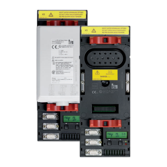
Funktion und Geräteaufbau Funktion Funktion Das CPU & Power Modul (CPM) 9440/22 hat die Funktion eines Gateways zwischen dem internen Bus einer IS1+ Feldstation und dem Feldbus, der die Feldstation einfach oder redundant mit dem Automatisierungssystem verbindet. Einsatzbereich Das CPM ist für IS1+ Feldstationen bestimmt und darf in explosionsgefährdeten Bereichen der Zone 1 / Division 1, Zone 2 / Division 2 oder Zone 21 und 22 sowie im sicheren Bereich installiert werden. -
Page 9: Technische Daten
Technische Daten Technische Daten Explosionsschutz Global (IECEx) IECEx KEM 08.0038X 9440/22-01-.1: Ex d [ia] [ib] IIC T4 Gb 9490/11-12: Ex d e [ia] [ib] IIC T4 Gb 9490/13-12: Ex d mb [ia] [ib] IIC T4 Gb Europa (ATEX) KEMA 02 ATEX 1333 X 9440/22-01-.1: E II 2 G Ex d [ia] [ib] IIC T4 Gb 9490/11-12:... - Page 10 Technische Daten Technische Daten Ausführung 9440/22-01-11 (24 V DC) 9440/22-01-21 (90 ... 253 V AC) Elektrische Daten Hilfsenergie Nennspannung 24 V DC 120 V / 230 V AC Spannungs- 20 ... 35 V DC 90 ... 253 V AC bereich Netzfrequenz –...
- Page 11 • Ausgänge lesen und schreiben • Diagnosedaten übertragen (z.B. Konfig-Fehler, Hardware-Fehler, Signal-Fehler) • HART-Kommandos von / zu HART-Feldgeräten übertragen Anschließbare • IS Wizard (über R. STAHL ServiceBus) Softwarepakete • R. STAHL DTM • AMS von Emerson Process Management • PDM von Siemens •...
- Page 12 Technische Daten Technische Daten Stromversorgung für I/O Module über die BusRail Spannungs- 22,5 ... 26,2 V DC bereich Max. Strom Max. Anzahl I/O-Module Redundante ja (mit Dioden entkoppelt) Versorgung der I/O-Module Unterspannungs- überwachung Galvanische Trennung zwischen 1500 V AC Hilfsenergie und System- komponenten zwischen...
- Page 13 (IEC 60529) Module IP30 Anschlüsse IP20 Montage / Installation Einbaubedingungen Montageart auf 35-mm-DIN-Schiene NS 35/15 Einbaulage waagrecht und senkrecht Weitere technische Daten, siehe www.r-stahl.com. 162277 / 9440607310 CPU & Power Modul für Zone 1 / Div. 1 2018-08-13·BA00·III·de·06 Reihe 9440/22, 9490...
-
Page 14: Projektierung
• Beim Einsatz in explosionsgefährdeten Bereichen müssen zwischen den Feldbus-Anschlüssen (X1, X2, X3) und dem Automatisierungssystem geeignete Feldbus-Trennübertrager eingesetzt werden (z.B. R. STAHL Reihe 9185 oder 9186). Dies gilt auch dann, wenn das CPU & Power Modul im sicheren Bereich installiert ist aber Feldbus-Stromkreise der angeschlossenen I/O-Module in den explosionsgefährdeten Bereich führen. -
Page 15: Hilfsenergieanschluss
Transport und Lagerung Hilfsenergieanschluss Für den Hilfsenergieanschluss stehen 2 verschiedene Sockel zur Verfügung: • 9490/11-12: Anschluss über Ex e Klemme • 9490/13-12: Anschluss über Kabelschwanz • 9490/12-12: Anschluss über Conduit Anschlussbelegung Ex e Klemme Kabelschwanz Funktion Klemmen Nr. Leiter Nr. +24 V DC N (90 ... -
Page 16: Montage Und Installation
Montage und Installation Montage und Installation Das Gerät ist für den Einsatz in gasexplosionsgefährdeten Bereichen der Zonen 1/ Division 1 und Zone 2/Division 2, in staubexplosionsgefährdeten Bereichen der Zonen 21 und 22 sowie auch im sicheren Bereich zugelassen. GEFAHR Explosionsgefahr bei Installation ohne Feldgehäuse! Nichtbeachten führt zu schweren oder tödlichen Verletzungen! •... -
Page 17: Maßangaben / Befestigungsmaße
Montage und Installation Maßangaben / Befestigungsmaße Maßzeichnungen (alle Maße in mm [Zoll]) – Änderungen vorbehalten 287 mm / 11.3 " 09877E00 07762E00 9490/11-12 9490/12-12 nur FM CPU & Power Modul für Zone 1 CPU & Power Modul für Division 1 mit Anschluss über Ex e Klemmen mit Anschluss über Conduit 07760E00... -
Page 18: Montage / Demontage, Gebrauchslage
Montage und Installation Montage / Demontage, Gebrauchslage 8.2.1 Montage / Demontage auf BusRail HINWEIS Fehlfunktion oder Geräteschaden durch unsachgemäße Montage. Nichtbeachten kann Sachschaden verursachen! • Gerät ausschließlich senkrecht montieren, mit Lese-Richtung der LCD-Anzeige wahlweise von unten, von links oder von rechts. Montage des Sockels auf BusRail •... - Page 19 Montage und Installation 8.2.2 Demontage / Modulwechsel WARNUNG Stromschlaggefahr durch spannungsführende Klemme! Nichtbeachten kann zu schweren Verletzungen und Sachschäden führen. • An den Ex e Klemmen oder am Kabelschwanz nur im spannungsfreien Zustand arbeiten. Austausch des CPM Moduls • Rasthebel in Position "II" schieben, Abbildung 1.
-
Page 20: 8.3 Installation
Montage und Installation Austausch des Sockels • CPM entnehmen, siehe Kapitel "Austausch des CPM Moduls". • Hilfsenergie von Ex e Klemme entfernen bzw. Kabelschwanz von Hilfsenergie trennen. • Feldbus-Anschlüsse von den Sub-D-Buchsen entfernen. • Klemmschrauben des Sockels lösen. 17943E00 • Sockel senkrecht von BusRail abziehen. -
Page 21: Parametrierung Und Inbetriebnahme
Parametrierung und Inbetriebnahme • Am Sockel darf entweder nur die Hilfsenergie 20 ... 35 V DC für das CPM 9440/22-01-11 oder 90 ... 230 V AC für das CPM 9440/22-01-21 angeschlossen werden. Der gleichzeitige Anschluss beider Hilfsenergien ist nicht zulässig. •... - Page 22 Parametrierung und Inbetriebnahme 9.1.1 StartUp Anzeige Einstellungen • Nach Anlegen der Hilfsenergie bootet das Gerät. FBAdr • Nach erfolgreichem Bootvorgang wechselt die LCD-Anzeige in die Systemebene (links dargestellt). 12258E00 9.1.2 Feldbusadresse einstellen Die Feldbusadresse kann nur eingestellt werden, wenn sich das Gerät nicht im Zustand Data Exchange befindet.
-
Page 23: Betrieb
Betrieb Betrieb 10.1 Betrieb Nach Montage, Installation und Inbetriebnahme (siehe Kapitel "Montage und Installation" und "Parametrierung und Inbetriebnahme") ist das CPU & Power Modul betriebsbereit. Weiterführende Dokumentation beachten (Kopplungsbeschreibung). Das CPM und die Sub-D-Stecker können während des Betriebs im explosionsgefährdeten Bereichen gefahrlos gesteckt oder gezogen werden (hot swap). - Page 24 Betrieb Anzeige Status-Informationen der CPM LCD-Anzeige Anzeige/Funktion Zustand und Feldbus-Adresse des Geräts. active FB addr : 12260E00 Kopplungsart information Modbus V10-00 12264E00 Status des Geräts. status config/para fail Mögliche Status-Informationen: 12265E00 Status-Information in LCD-Anzeige Bedeutung no error kein Fehler hardware fail (1) Hardwarefehler gefunden hardware fail (2) falsche Hardware-Kennung...
- Page 25 Betrieb Anzeige Status-Informationen der Input-/Output-Module Die folgenden Anzeigen sind für alle Input/Output-Module gleich aufgebaut. LCD-Anzeige Anzeige/Funktion Anzeige des Steckplatzes, des Modultyps und des Modulzustands. slot module OK/mode:0 Mögliche Modulzustände: 12268E00 Status-Information in Bedeutung Prio LCD-Anzeige IOM no response Kommunikation mit dem Modul ist nicht möglich.
- Page 26 Betrieb Digital-Module Zusätzlich zu den allgemeinen Anzeigen gibt es bei Digital-Modulen noch folgende Anzeigen: LCD-Anzeige Anzeige/Funktion Ohne Ausgabedaten wird Sicherheitszustand der Ausgänge angezeigt. slot (nur bei Output-Module) safety position 12272E00 IO-Fehler. slot : Drahtbruch : Kurzschluss 12273E00 IO-Daten und -Fehler. 1 1 0 0 1 0 1 1 12274E00 IO-Daten.
- Page 27 Betrieb Analog-Module mit HART Für das HART-Modul 9468 können die HART PV dargestellt werden. Das Untermenü erscheint nur, wenn die Analog-Module für die Übertragung von HART PV konfiguriert sind. Es werden nur die konfigurierten HART PV angezeigt. LCD-Anzeige Anzeige/Funktion Menü zur Anzeige der HART PV. slot Aufruf der Untermenüs durch gleichzeitiges Drücken von ▲...
-
Page 28: Fehlerbeseitigung
CPM richtig auf BusRail aufrasten. • CPM tauschen. Wenn sich der Fehler mit den genannten Vorgehensweisen nicht beheben lässt: • An R. STAHL Schaltgeräte GmbH wenden. Zur schnellen Bearbeitung folgende Angaben bereithalten: • Typ und Seriennummer des Geräts • Kaufdaten •... -
Page 29: Instandhaltung, Wartung, Reparatur
GEFAHR Explosionsgefahr durch unsachgemäße Reparatur! Nichtbeachten führt zu schweren oder tödlichen Verletzungen. • Reparaturen an den Geräten ausschließlich durch R. STAHL Schaltgeräte GmbH ausführen lassen. 162277 / 9440607310 CPU & Power Modul für Zone 1 / Div. 1 2018-08-13·BA00·III·de·06 Reihe 9440/22, 9490... -
Page 30: Rücksendung
Reinigung 11.4 Rücksendung • Rücksendung bzw. Verpackung der Geräte nur in Absprache mit R. STAHL durchführen! Dazu mit der zuständigen Vertretung von R. STAHL Kontakt aufnehmen. Für die Rücksendung im Reparatur- bzw. Servicefall steht der Kundenservice von R. STAHL zur Verfügung. - Page 31 Operating instructions Additional languages www.r-stahl.com CPU & Power Module for Zone 1 / Div. 1 Series 9440/22, 9490...
- Page 32 Contents General Information ....................3 Manufacturer .......................3 Information regarding the Operating Instructions ..........3 Further Documents .....................3 Conformity with Standards and Regulations ............3 Explanation of the Symbols ................4 Symbols in these Operating Instructions ............4 Warning Notes ....................4 Symbols on the Device ..................5 Safety Notes .......................5 Operating Instructions Storage ................5 Personnel Qualification ..................5...
-
Page 33: En En
• Data sheet For documents in additional languages, see www.r-stahl.com. Conformity with Standards and Regulations See certificates and EU Declaration of Conformity: www.r-stahl.com. The device has IECEx approval. For certificate please refer to the IECEx homepage: http://iecex.iec.ch/ Further national certificates can be downloaded via the following link: https://r-stahl.com/en/global/products/support/downloads/. -
Page 34: Explanation Of The Symbols
Explanation of the Symbols Explanation of the Symbols Symbols in these Operating Instructions Symbol Meaning Tips and recommendations on the use of the device Danger due to explosive atmosphere Danger due to live components Warning Notes Warnings must be observed under all circumstances, in order to minimize the risk due to construction and operation. -
Page 35: Symbols On The Device
Specialists who perform these tasks must have a level of knowledge that meets applicable national standards and regulations. Additional knowledge is required for tasks in hazardous areas! R. STAHL recommends having a level of knowledge equal to that described in the following standards: •... -
Page 36: 3.3 Safe Use
• Use the device in accordance with its intended and approved purpose only. • Always consult with R. STAHL Schaltgeräte GmbH if using the device under operating conditions which are not covered by the technical data. • Before installation, make sure that the device is not damaged. -
Page 37: Modifications And Alterations
Function and Device Design Commissioning, maintenance, repair • Only have commissioning and repairs performed by qualified and authorised persons (see chapter "Personnel qualification"). • Before commissioning, make sure that the device is not damaged. • Perform only maintenance work described in these operating instructions. •... -
Page 38: Function
Function and Device Design Function Function The CPU & power module (CPM) 9440/22 fulfils the function of a gateway between the internal bus of an IS1+ field station and the fieldbus which connects the field station singly or redundantly to the automation system. Application range The CPM is designed for IS 1+ field stations and may be installed in hazardous areas of Zone 1 / Division 1, Zone 2 / Division 2 or Zone 21 and 22 and in safe areas. -
Page 39: Technical Data
Technical Data Technical Data Explosion Protection Global (IECEx) IECEx KEM 08.0038X 9440/22-01-.1: Ex d [ia] [ib] IIC T4 Gb 9490/11-12: Ex d e [ia] [ib] IIC T4 Gb 9490/13-12: Ex d mb [ia] [ib] IIC T4 Gb Europe (ATEX) KEMA 02 ATEX 1333 X 9440/22-01-.1: E II 2 G Ex d [ia] [ib] IIC T4 Gb 9490/11-12:... - Page 40 Technical Data Technical Data Design 9440/22-01-11 (24 V DC) 9440/22-01-21 (90 to 253 V AC) Electrical data Auxiliary power Nominal voltage 24 V DC 120 V / 230 V AC Voltage range 20 to 35 V DC 90 to 253 V AC Mains frequency –...
- Page 41 • Read and write outputs • Transfer diagnostic (e.g. config. error, hardware error, signal error) • Transfer HART commands to/from HART field devices. • Connectable • IS Wizard (via R. STAHL ServiceBus)■■■■■■■■■■ software packages • R. STAHL DTM • AMS by Emerson Process Management •...
- Page 42 Technical Data Technical Data Power supply for the I/O modules via the BusRail Voltage range 22.5 ... 26.2 V DC Max. current Max. number I/O modules Redundant supply yes (decoupled with diodes) of the I/O modules Undervoltage monitoring Galvanic separation between power 1500 V AC supply and system...
- Page 43 Mounting / Installation Installation conditions Mounting type on 35 mm DIN rail NS 35/15 Mounting horizontal and vertical orientation For further technical data, see www.r-stahl.com. 162277 / 9440607310 CPU & Power Module for Zone 1 / Div. 1 2018-08-13·BA00·III·en·06 Series 9440/22, 9490...
-
Page 44: Engineering
• If used in hazardous areas, suitable fieldbus isolating repeaters must be used between the fieldbus connections (X1, X2, X3) and the automation system (e.g. R. STAHL Series 9185 or 9186). This also applies when the CPU & power module is installed in a safe area but fieldbus circuits of the connected I/O modules feed into the hazardous area. -
Page 45: Auxiliary Power Connection
Transport and Storage Auxiliary Power Connection For the auxiliary power connection there are 2 different bases available: • 9490/11-12: Connection by means of Ex e terminal • 9490/13-12: Connection by means of an unconnected cable end • 9490/12-12: Connection by means of conduit Terminal assignment Ex e terminal Unconnected cable end... -
Page 46: Mounting And Installation
Mounting and Installation Mounting and Installation The device is approved for use in gas explosion hazardous areas of Zone 1/Division 1 and Zone 2/Division 2, in dust explosion hazardous areas of Zones 21 and 22 and in safe areas. DANGER Explosion hazard due to installation without field enclosure! Non-compliance results in severe or fatal injuries! •... -
Page 47: Dimensions / Fastening Dimensions
Mounting and Installation Dimensions / Fastening Dimensions Dimensional drawings (all dimensions in mm [inches]) – Subject to alterations 287 mm / 11.3 " 09877E00 07762E00 9490/11-12 9490/12-12 only FM CPU & power module for Zone 1 CPU & power module for Division 1 with connection by means of Ex e terminals with connection by means of a conduit 07760E00... -
Page 48: Mounting / Dismounting, Operating Position
Mounting and Installation Mounting / Dismounting, Operating Position 8.2.1 Mounting / Dismounting on BusRail NOTICE Malfunction or device damage caused by improper mounting. Non-observance can result in material damage! • Mount the device in vertical direction only, with the reading direction of the LCD display from below, left or right, as desired. - Page 49 Mounting and Installation 8.2.2 Dismounting / Replacement of the Module WARNING Risk of electric shock due to live terminal! Non-compliance can result in severe injuries and material damage. • Work on the Ex e terminals or unconnected cable end only if de-energised.
-
Page 50: 8.3 Installation
Mounting and Installation Replacing the base • Remove the CPM, see the "Replacing the CPM module" chapter. • Remove the auxiliary power from the Ex e terminal or disconnect the unconnected cable end from the auxiliary power. • Remove the fieldbus connections from the Sub-D sockets. -
Page 51: Parameterization And Commissioning
Parameterization and Commissioning • Either only the auxiliary power 20 to 35 V DC for the CPM 9440/22-01-11 or 90 to 230 V AC for the CPM 9440/22-01-21 may be connected to the base. Simultaneous connection of both auxiliary powers is not permitted. •... - Page 52 Parameterization and Commissioning 9.1.1 Start-up Display Settings • After connecting the auxiliary power, the device will boot. FBAdr • After successful completion of the booting process, the LCD display switches to the system level (shown on the left). 12258E00 9.1.2 Setting the Fieldbus Address The fieldbus address can be set only if the device is not in the Data Exchange mode.
-
Page 53: Operation
Operation Operation 10.1 Operation After mounting, installation and commissioning (see the "Mounting and installation" and "Parameterization and commissioning" chapters) the CPU & power module is ready for operation. Please observe the additional documentation (coupling description) The CPM and the Sub-D connectors can be plugged or unplugged safely during operation in hazardous areas (hot swap). - Page 54 Operation Display of the CPM status information LCD display Display/function Status and fieldbus address of the device active FB addr : 12260E00 Type of coupling information Modbus V10-00 12264E00 Status of the device. status config/para fail Possible status information: 12265E00 Status information on the LCD display Meaning no error...
- Page 55 Operation Displaying status information of the input / output modules The following displays show the same design for all output/input modules. LCD display Display/function Display of the slot, module type and module status. slot module OK/mode:0 Possible module statuses: 12268E00 Status information on Meaning Prio...
- Page 56 Operation Digital modules In addition to the general displays, digital modules also exhibit the following displays: LCD display Display/function In the absence of output data, the safety status of the outputs is displayed. slot (for output module only) safety position 12272E00 IO error.
- Page 57 Operation Analog modules with HART For HART Module 9468, the HART PV can be displayed. The submenu appears only if the analog modules have been configured for HART PV transmission. Only configured HART PVs are displayed. LCD display Display/function Menu for displaying the HART PV. slot To display the submenu, press ▲...
-
Page 58: Troubleshooting
BusRail. • Replace CPM. If the error cannot be eliminated using the mentioned procedures: • Contact R. STAHL Schaltgeräte GmbH. For fast processing, have the following information ready: • Type and serial number of the device • Purchase information • Error description •... -
Page 59: Maintenance, Overhaul, Repair
Explosion hazard due to improper repair! Non-compliance results in severe or fatal injuries. • Repair work on the devices must be performed only by R. STAHL Schaltgeräte GmbH. 162277 / 9440607310 CPU & Power Module for Zone 1 / Div. 1 2018-08-13·BA00·III·en·06... -
Page 60: Returning The Device
• Only return or package the devices after consulting R. STAHL! Contact the responsible representative from R. STAHL. R. STAHL's customer service is available to handle returns if repair or service is required. • Contact customer service personally. • Go to the www.r-stahl.com website. - Page 62 Class I, DIV 2 / Zone 1 Installation The CPM types 9440/22-01-*1 are Explosion-proof modules for for connection to I/O Modules located in installation in Class I, Division 1 or Division 2, Group A-D or Class I, Class I, II, III, Division 2, Group A-G, Zone 1, Group IIC/IIB areas;...
- Page 63 Notes: Connect either power supply 20... 35 V DC for the CPM 9440/22-01-11 or power supply 90…253 V AC for the CPM 9440/22-01-21. Never connect both power supply voltages. Insulate unused wire. Electrical Apparatus connected to an intrinsically safe system should not use or generate voltages > 253 V AC (U The CPM may be detached from the Socket or plugged onto it during operation in hazardous locations.
- Page 64 Example for Fieldbus System Topology with Bus Isolators The IS1 resp. IS1+ Remote I/O is a DIN rail mounted system designed interfacing Automation control systems with DIV 1 / Zone 1 to record and output process control signals between hazardous installation of IS1 resp.
- Page 65 Block Diagram of an RS485 Field Station: I.S. Inputs and Outputs Class I, II, III, DIV 1, Groups A-G; Class I, Zone 0, IIC/IIB or Non I.S. or Nonincendive circuits, Class I, II, III, DIV 2, Group A-G; Class I, Zone 2, Group IIC/IIB Block Diagram of an Ethernet Field Station: I.S.
- Page 66 National Electrical Code, ANSI/NFPA 70 Article 500 or Canadian Electrical Code, CSA C22. Installation with the use of an appropriate fieldbus isolator for nonincendive fieldbus circuits (e.g. R. STAHL type 9185). The Ethernet interface is achieved with the use of media converters and switches providing optical Ethernet.
- Page 67 Block Diagram of an RS485 Field Station: I.S. Inputs and Outputs Class I, II, III, DIV 1, Groups A-G; Class I, Zone 0, IIC/IIB or Non I.S. or Nonincendive circuits, Class I, II, III, DIV 2, Group A-G; Class I, Zone 2, Group IIC/IIB Block Diagram of an Ethernet Field Station: I.S.
- Page 68 Fieldbus Isolating Repeater Type 9185/11-35-10 Connections: X3, Pin 3, 5, 6, 8 Terminating resistor Z: value > 143 ohms + 1%, > 400 mW, with a thermal rating of 140 K/W. This resistor is included in the STAHL Entity parameters: Fieldbus connector.
Need help?
Do you have a question about the 9440/22 Series and is the answer not in the manual?
Questions and answers