Chapters
Table of Contents

Related Manuals for Stahl IS1+ 9475/32-04-72 Series


Summary of Contents for Stahl IS1+ 9475/32-04-72 Series
- Page 1 Betriebsanleitung Additional languages r-stahl.com Digital Output Modul 4-Kanal-Ausführung für Zone 1 Reihe 9475/32-04-72...
-
Page 2: Table Of Contents
Inhaltsverzeichnis Allgemeine Angaben ...................3 Hersteller ......................3 Angaben zur Betriebsanleitung ................3 Weitere Dokumente ....................3 Konformität zu Normen und Bestimmungen ............3 Erläuterung der Symbole ..................3 Symbole in der Betriebsanleitung ...............3 Warnhinweise .....................4 Symbole am Gerät ....................4 Sicherheitshinweise ....................5 Aufbewahrung der Betriebsanleitung ..............5 Qualifikation des Personals ................5 Sichere Verwendung ...................5 Umbauten und Änderungen ................6... -
Page 3: De De
Die Originalbetriebsanleitung ist die englische Ausgabe. Diese ist rechtsverbindlich in allen juristischen Angelegenheiten. Weitere Dokumente • Kopplungsbeschreibung IS1+ (Download unter r-stahl.com) • Anleitung "Erdung und Schirmung" (Download unter r-stahl.com) • Datenblatt Dokumente in weiteren Sprachen, siehe r-stahl.com. Konformität zu Normen und Bestimmungen Zertifikate und EU-Konformitätserklärung, siehe r-stahl.com. -
Page 4: 2.2 Warnhinweise
Erläuterung der Symbole Warnhinweise Warnhinweise unbedingt befolgen, um das konstruktive und durch den Betrieb bedingte Risiko zu minimieren. Die Warnhinweise sind wie folgt aufgebaut: • Signalwort: GEFAHR, WARNUNG, VORSICHT, HINWEIS • Art und Quelle der Gefahr/des Schadens • Folgen der Gefahr •... -
Page 5: Sicherheitshinweise
Normen und Bestimmungen umfasst. Für Tätigkeiten in explosionsgefährdeten Bereichen sind weitere Kenntnisse erforderlich! R. STAHL empfiehlt einen Kenntnisstand, der in folgenden Normen beschrieben wird: • IEC/EN 60079-14 (Projektierung, Auswahl und Errichtung elektrischer Anlagen) • IEC/EN 60079-17 (Prüfung und Instandhaltung elektrischer Anlagen) •... -
Page 6: Umbauten Und Änderungen
Sicherheitshinweise • Module und Steckverbinder dürfen im Betrieb in explosionsgefährdeten Bereichen gesteckt und getrennt werden (hot-swap und hot-plug). • Bei Einsatz in Zone 1, 2, 21 oder Zone 22 ist das Gerät in ein schützendes Gehäuse oder einen Schrank entsprechend der IEC/EN 60079-0 einzubauen, die eine geeignete Schutzart bieten. -
Page 7: Funktion Und Geräteaufbau
Funktion und Geräteaufbau Funktion und Geräteaufbau GEFAHR Explosionsgefahr durch zweckentfremdete Verwendung! Nichtbeachten führt zu schweren oder tödlichen Verletzungen. • Gerät nur entsprechend den in dieser Betriebsanleitung festgelegten Betriebsbedingungen verwenden. • Gerät nur entsprechend dem in dieser Betriebsanleitung genannten Einsatzzweck verwenden. Funktion Einsatzbereich Das Digital Output Modul Typ 9475/32-04-72 kann, bei Einbau in ein entsprechend... -
Page 8: Geräteaufbau
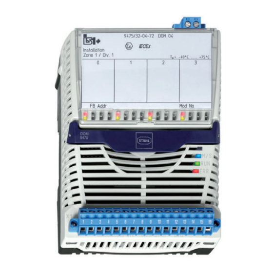
Funktion und Geräteaufbau Geräteaufbau Gerätelement Beschreibung Abdeckung Abdeckung mit Einlegeschild (geöffnet) und Anschlussplan Beschriftung Angaben zum Modul (Seriennummer, Hardware-Revisionsnummer, Software-Revisionsnummer, Herstelldatum, z.B.: 123456DE9999 15320E00 Rev.A 01-01 0508) LEDs (rot) zur Fehleranzeige (Drahtbruch/Kurzschluss) je Kanal; LEDs (gelb) zur Statusanzeige (AN/AUS) je Kanal und "Anlagen-AUS"... -
Page 9: Technische Daten
Technische Daten Technische Daten Explosionsschutz Global (IECEx) Gas und Staub IECEx DEK 12.0070X Ex ia [ib Gb] IIC T4 Gb [Ex ib Db] IIIC Europa (ATEX) Gas und Staub DEKRA 12 ATEX0232X E II 2 (2) G Ex ia [ib Gb] IIC T4 Gb E II (2) D [Ex ib Db] IIIC Bescheinigungen und Zertifikate Bescheinigungen... - Page 10 Technische Daten Explosionsschutz Max. innere 33 nF (in den obigen Tabellen ist C von C abgezogen) Kapazität C Max. innere vernachlässigbar Induktivität L Ex i Steuereingang "Anlagen-AUS" Anschluss- X3 1, 2 X3 3, 4 klemmen (ohne galvanische (mit galvanischer Trennung, Trennung, 9475/22 kompatibel) parallel schaltbar)
- Page 11 Technische Daten Technische Daten Elektrische Daten Ausführung 3 Kanäle mit 9475/32-04-72 4 Kanäle mit 9475/32-04-72 Ex i Ausgänge Anzahl Kanäle Leerlaufspannung 13,8 V 13,8 V Ausgangs- 95 mA 75 mA nennstrom Innenwiderstand 23,2 Ω 23,2 Ω Nennbetrieb 11,7 V 12,3 V 95 mA 75 mA Ausgangs-...
- Page 12 Technische Daten Technische Daten Galvanische Trennung Prüfspannung gemäß Norm EN 60079-11 Zwischen ) 1500 V AC Hilfsenergie / System- komponenten Zwischen zwei ) 500 V AC I/O-Modulen Zwischen ) 500 V AC I/O-Kanälen / System- komponenten Zwischen ) 500 V AC I/O-Kanälen / Erde (PA) Zwischen...
- Page 13 Technische Daten Technische Daten Hilfsenergie Ausführung Eigensicher Ex ia über BusRail Verhalten bei alle Ausgänge "AUS" Unterspannung Max. 250 mA Stromaufnahme Max. Leistungs- aufnahme Max. 5,8 W Verlustleistung Max. 3,4 W Verlustleistung im Nennbetrieb Gerätespezifische Daten Einstellungen Modul Diagnose- EIN / AUS Meldungen Signal Leitungsfehler-...
- Page 14 (nur bei eingeschaltetem Ausgang erkennbar) Montage / Installation Einbaulage waagrecht oder senkrecht (Betriebsanleitung beachten) Montageart auf 35-mm-DIN-Schiene NS 35/15 (DIN EN 60715) Weitere technische Daten, siehe r-stahl.com. Digital Output Modul 4-Kanal-Ausführung 221672 / 9475626310 für Zone 1 2019-01-18·BA00·III·de·02 Reihe 9475/32-04-72...
-
Page 15: Projektierung
Projektierung Projektierung HINWEIS Ausfall der installierten Geräte im Schaltschrank durch zu hohe Umgebungstemperatur! Nichtbeachten kann zu Sachschäden führen. Schaltschrank so aufbauen und einrichten, dass er immer innerhalb des • zulässigen Temperaturbereichs betrieben wird. Bei der Projektierung folgende Bedingungen beachten: • Installation des Geräts zur bestimmungsgemäßen Verwendung nur auf der IS1 BusRail 9494. -
Page 16: Leitungsfehlerunterdrückung
Projektierung Die Module haben zusätzlich eine steckbare Klemme X3 zum Anschluss an den Stromkreis "Anlagen-AUS". Die steckbare Klemme X3 hat 2 Klemmen. Sie kann entweder in X3.1, X3.2 (Kontakt) oder X3.3, X3.4 (aktiver Eingang) am Modul gesteckt werden. Ein gleichzeitiges Stecken von Klemmen in X3.1, X3.2 und X3.3, X3.4 ist nicht möglich. -
Page 17: 7 Transport Und Lagerung
Transport und Lagerung Transport und Lagerung • Gerät nur in Originalverpackung transportieren und lagern. • Gerät trocken (keine Betauung) und erschütterungsfrei lagern. • Gerät nicht stürzen. Montage und Installation Das Gerät ist für den Einsatz in gasexplosionsgefährdeten Bereichen der Zonen 1 und 2, in staubexplosionsgefährdeten Bereichen der Zonen 21 und 22 sowie auch im sicheren Bereich zugelassen. -
Page 18: Montage / Demontage, Gebrauchslage
Montage und Installation Montage / Demontage, Gebrauchslage 8.2.1 Montage / Demontage HINWEIS Fehlfunktion oder Geräteschaden durch unsachgemäße Montage. Nichtbeachten kann Sachschaden verursachen! • Gerät nur in vertikaler oder horizontaler Lage montieren und betreiben! (Orientierung horizontal: Lese-Richtung von unten) Montage auf BusRail •... - Page 19 Montage und Installation 8.2.2 Demontage / Modulwechsel Hot-Swap / Hot-Plug Das Modul und die steckbaren Klemmen X1 und X3 können während des Betriebs im explosionsgefährdeten Bereich gefahrlos gesteckt oder gezogen werden. Demontage • Schrauben der steckbaren Klemmen X1 und X3 lösen. •...
-
Page 20: 8.3 Installation
Inbetriebnahme Installation Bei Betrieb unter erschwerten Bedingungen wie insbesondere auf Schiffen sind zusätzliche Maßnahmen zur korrekten Installation je nach Einsatzort zu treffen. Weitere Informationen und Anweisungen hierzu erhalten Sie gerne auf Anfrage von Ihrem zuständigen Vertriebskontakt. In der Abdeckklappe befindet sich ein Einlegeschild, in das die Zuordnung der Feldgeräte zu den Kanälen eingetragen werden kann. -
Page 21: Anzeigen
Betrieb Betrieb 10.1 Anzeigen Entsprechende LEDs am Gerät zeigen den Betriebszustand des Geräts an (siehe auch Kapitel "Funktion und Geräteaufbau"). Farbe Bedeutung LED "RUN" grün Betriebsanzeige LED "ERR" Anzeige Modulfehler LED "M/S" blau Wartungsbedarf oder außerhalb Spezifikation 4 x LED Fehler im jeweiligen Feldstromkreis 4 + 1 x LED gelb... - Page 22 4 + 1 x LED erloschen Kein Ausgangssignal – (hochohmig) Wenn sich der Fehler mit den genannten Vorgehensweisen nicht beheben lässt: • An R. STAHL Schaltgeräte GmbH wenden. Zur schnellen Bearbeitung folgende Angaben bereithalten: • Typ und Seriennummer des Geräts • DCS/SPS • Protokoll •...
-
Page 23: Instandhaltung, Wartung, Reparatur
11.3 Reparatur GEFAHR Explosionsgefahr durch unsachgemäße Reparatur! Nichtbeachten führt zu schweren oder tödlichen Verletzungen. • Reparaturen an den Geräten ausschließlich durch R. STAHL Schaltgeräte GmbH ausführen lassen. 221672 / 9475626310 Digital Output Modul 4-Kanal-Ausführung 2019-01-18·BA00·III·de·02 für Zone 1 Reihe 9475/32-04-72... -
Page 24: Rücksendung
Reinigung 11.4 Rücksendung • Rücksendung bzw. Verpackung der Geräte nur in Absprache mit R. STAHL durchführen! Dazu mit der zuständigen Vertretung von R. STAHL Kontakt aufnehmen. Für die Rücksendung im Reparatur- bzw. Servicefall steht der Kundenservice von R. STAHL zur Verfügung. - Page 25 Operating instructions Additional languages r-stahl.com Digital Output Module 4-Channel Version for Zone 1 Series 9475/32-04-72...
- Page 26 Contents General Information ....................3 Manufacturer .......................3 Information regarding the Operating Instructions ..........3 Further Documents .....................3 Conformity with Standards and Regulations ............3 Explanation of the Symbols ................3 Symbols in these Operating Instructions ............3 Warning Notes ....................4 Symbols on the Device ..................4 Safety Notes .......................5 Operating Instructions Storage ................5 Personnel Qualification ..................5...
-
Page 27: En En
They are legally binding in all legal affairs. Further Documents • IS1+ coupling description (download from r-stahl.com) • "Earthing and shielding" instructions (download from r-stahl.com) • Data sheet For documents in additional languages, see r-stahl.com. Conformity with Standards and Regulations See certificates and EU Declaration of Conformity: r-stahl.com. -
Page 28: 2.2 Warning Notes
Explanation of the Symbols Warning Notes Warnings must be observed under all circumstances, in order to minimize the risk due to construction and operation. The warning notes have the following structure: • Signalling word: DANGER, WARNING, CAUTION, NOTICE • Type and source of danger/damage •... -
Page 29: Safety Notes
• Use the device in accordance with its intended and approved purpose only. • Always consult with R. STAHL Schaltgeräte GmbH if using the device under operating conditions which are not covered by the technical data. • Before installation, make sure that the device is not damaged. -
Page 30: Modifications And Alterations
Safety Notes • Modules and plug connectors may be connected and disconnected during operation in hazardous areas (hot swap and hot plug). • When used in Zone 1, 2, 21 or 22, the device is to be installed in a protective enclosure or in a cabinet that offers a suitable degree of protection in accordance with IEC/EN 60079-0. -
Page 31: Function And Device Design
Function and Device Design Function and Device Design DANGER Explosion hazard due to improper use! Non-compliance results in severe or fatal injuries. • Use the device only in accordance with the operating conditions described in these operating instructions. • Use the device only for the intended purpose specified in these operating instructions. -
Page 32: Device Design
Function and Device Design Device Design Device component Description Covering Covering with insert disc (open) and connection diagram Labelling Module data (Serial number, hardware revision number, software revision number, date of manufacture, e.g.: 123456DE9999 15320E00 Rev.A 01-01 0508) LEDs (red) for error indication (wire breakage/short circuit) for each channel;... -
Page 33: Technical Data
Technical Data Technical Data Explosion Protection Global (IECEx) Gas and dust IECEx DEK 12.0070X Ex ia [ib Gb] IIC T4 Gb [Ex ib Db] IIIC Europe (ATEX) Gas and dust DEKRA 12 ATEX0232X E II 2 (2) G Ex ia [ib Gb] IIC T4 Gb E II (2) D [Ex ib Db] IIIC Certifications and certificates Certificates... - Page 34 Technical Data Explosion Protection Max. internal 33 nF (in the above tables, C is subtracted from C capacity C Max. internal negligible inductance L Ex i control input "Plant STOP" Connection X3 1, 2 X3 3, 4 terminals (without galvanic (with galvanic separation, separation,...
- Page 35 Technical Data Technical Data Electrical data Version 3 channels with 9475/32-04-72 4 channels with 9475/32-04-72 Ex i outputs Number of channels Open-circuit 13.8 V 13.8 V voltage Output nominal 95 mA 75 mA current Internal resistance 23.2 Ω 23.2 Ω Rated operation 11.7 V 12.3 V...
- Page 36 Technical Data Technical Data Galvanic separation Test voltage acc. to standard EN 60079-11 Between ) 1500 V AC auxiliary power / system components Between two ) 500 V AC I/O modules Between ) 500 V AC I/O channels / system components Between ) 500 V AC...
- Page 37 Technical Data Technical Data Auxiliary power Version Intrinsically safe Ex ia via BusRail Behaviour during all outputs "OFF" undervoltage Max. current 250 mA consumption Max. power consumption Max. power 5.8 W dissipation Max. power 3.4 W dissipation in rated operation Device-specific data Settings Module...
- Page 38 Mounting / Installation Mounting orientation horizontal or vertical (observe operating instructions) Mounting type on 35 mm DIN rail NS 35/15 (DIN EN 60715) For further technical data, see r-stahl.com. Digital Output Module 4-Channel Version 221672 / 9475626310 for Zone 1 2019-01-18·BA00·III·en·02...
-
Page 39: Engineering
Engineering Engineering NOTICE An ambient temperature that is too high may cause failure of the devices installed in the cabinet. Non-compliance can result in material damage. • Install and adjust the cabinet in such a way that it is always operated within the permissible temperature range. -
Page 40: Line Fault Suppression
Engineering The modules also have a pluggable terminal X3 to connect to the "Plant STOP" electrical circuit. The pluggable terminal X3 has 2 terminals. It can either be inserted into X3.1, X3.2 (contact) or X3.3, X3.4 (active input) at the module. Simultaneous insertion of terminals into X3.1, X3.2 and X3.3, X3.4 is not possible. -
Page 41: 7 Transport And Storage
Transport and Storage Transport and Storage • Transport and store the device only in the original packaging. • Store the device in a dry place (no condensation) and vibration-free. • Do not drop the device. Mounting and Installation The device is approved for use in gas explosion hazardous areas of Zones 1 and 2 and dust explosion hazardous area of Zones 21 and 22 and in safe areas. -
Page 42: Mounting / Dismounting, Operating Position
Mounting and Installation Mounting / Dismounting, Operating Position 8.2.1 Mounting / Dismounting NOTICE Malfunction or device damage caused by improper mounting. Non-compliance may lead to material damage! • Only install and operate the device in a vertical or horizontal position! (Horizontal orientation: Reading direction from below) Mounting on BusRail •... - Page 43 Mounting and Installation 8.2.2 Dismounting / Replacement of the Module Hot swap / hot plug The module and the pluggable terminals X1 and X3 can be safely connected or disconnected during operation in the hazardous area. Dismounting • Loosen the screws of pluggable terminals X1 and X3. •...
-
Page 44: 8.3 Installation
Commissioning Installation Operation under difficult conditions, such as, in particular, on ships, requires additional measures to be taken for correct installation, depending on the place of use. Further information and instructions on this can be obtained from your regional sales contact on request. The cover flap features an insert disc which can be used to enter the assignment of the field devices to the channels. -
Page 45: Indications
Operation Operation 10.1 Indications The corresponding LEDs on the device indicate the operating state of the device (see also the "Function and device design" section). Colour Meaning "RUN" LED green Operation indication "ERR" LED Module error indication "M/S" LED blue Requires maintenance or outside specification 4 x LEDs Error in the respective field circuit... - Page 46 No output signal – (high-impedance) If the error cannot be eliminated using the specified procedures: • Contact R. STAHL Schaltgeräte GmbH. For rapid processing, have the following information ready: • Type and serial number of the device • DCS/PLC • Protocol •...
-
Page 47: Maintenance, Overhaul, Repair
DANGER Explosion hazard due to improper repair! Non-compliance results in severe or fatal injuries. • Repair work on the devices must be performed only by R. STAHL Schaltgeräte GmbH. 221672 / 9475626310 Digital Output Module 4-Channel Version 2019-01-18·BA00·III·en·02 for Zone 1... -
Page 48: Returning The Device
• Only return or package the devices after consulting R. STAHL! Contact the responsible representative from R. STAHL. R. STAHL's customer service is available to handle returns if repair or service is required. • Contact customer service personally. • Go to the r-stahl.com website. - Page 50 9475/32-04-7*: The Type 9475 Digital Output Module is designed to receive a digital Nonhazardous signal from the IS1 CPU & Power Module and output a corresponding Class I, II, III, Division 2, Group A-G discrete signal to solenoid valves, LED initiators and audible alarms. or Class I, Zone 1, Group IIC/IIB The module 9475/32-04-7* is intrinsically safe for installation in a Class Hazardous (Classified) Locations...
- Page 51 Capacitance and Inductance values for circuit with concentrated inductors and capacitors The internal capacitance per channel is already taken into account in the La and Ca values shown in the tables below. The internal inductance is negligibly small. Type 9475/3*-04-7* Capacitance and Inductance values Type 9475/3*-04-7* remaining capacitance and inductance values taking into account the cable connected CL I, DIV 2, Group A,B...
Need help?
Do you have a question about the IS1+ 9475/32-04-72 Series and is the answer not in the manual?
Questions and answers