Table of Contents
Advertisement
Advertisement
Table of Contents

Related Manuals for Stahl SLE22


Summary of Contents for Stahl SLE22
- Page 1 SLE22 Translation of Original Operating Instructions...
-
Page 2: Table Of Contents
Residual dangers ........................................7 General description, function ....................................9 Description ..........................................9 Load sensor ..........................................9 Frontal view ..........................................9 Block circuit diagram of SLE22 ..................................10 Simplified circuit diagram ....................................10 Safety functions ........................................11 3.6.1 Overload cut-off ......................11 3.6.2... -
Page 3: General Information
General information General information General information on operating instructions These operating instructions form an integral part of the SLE22 electronic control device for the manufacturer's hoists. It is addressed to hoist manufacturers, users, operators, commissioning engineers and service personnel. It must be available to the machinery manufacturer's or operator's technical personnel during the whole period of use for erection, electrical installation, configuration, commis- sioning, maintenance and diagnosis, and be observed by them. -
Page 4: Symbols
General information Symbols In these instructions, the safety notices are classified according to the severity of the danger and the probability of its occurrence. The procedures described for avoiding danger must be followed without fail. DANGER This symbol gives warning of an imminent danger to health and life. Ignoring these warning notices will lead to severe injuries, possibly resulting in death. -
Page 5: Target Group
General information Target group NOTICE All installation work and elimination of faults must be carried out by a skilled electri- cian, commissioning and maintenance by a qualified person. The following must be observed • EN 60204-1 and 32 • DIN VDE 0100 •... -
Page 6: Commissioning / Operation / Documentation
Commissioning / operation / documentation NOTICE The SLE22 does not fulfil its safety function until it has been programmed accordingly. Commissioning a hoist must be documented. This documentation must also include the overload cut-off point. It must be signed by the qualified person and the user after commissioning (Chapter 5: Commissioning and testing). -
Page 7: General Safety Instructions
General safety instructions General safety instructions DANGER Observe the safety information without fail: • National and international directives and regulations must be observed for erection, commissioning, operation and periodic tests, in particular the Machinery Directive 2006/42/EC, the directive for the use of work equipment 89/655/EEC, safety regula- tions and relevant national safety regulations. - Page 8 DANGER Failure of one of the downstream power devices: • Downstream power devices are not monitored by the SLE22. • Failure must be prevented by the designer of the control selecting appropriate devices • If a device fails the user must have it replaced immediately by a qualified person.
-
Page 9: General Description, Function
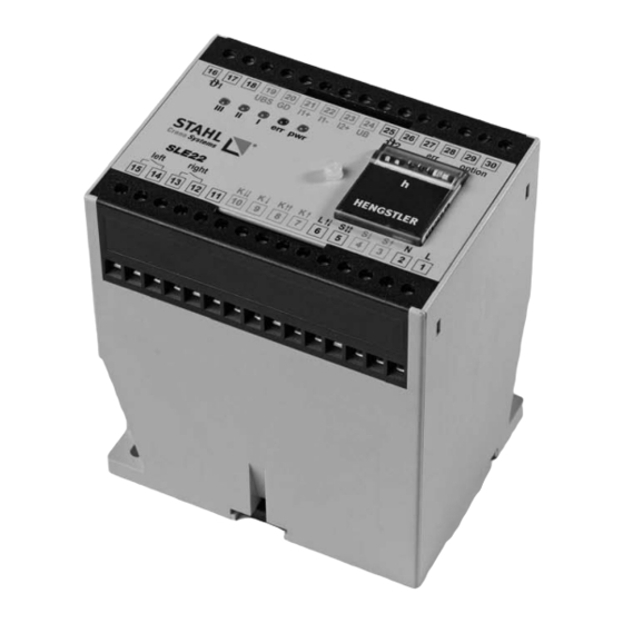
General description, function Description The SLE22 is an electronic control device for hoists. The device can be used to control pole-changing or frequency-controlled drives. It comprises a safety-oriented overload cut- off for hoists in conjunction with a load sensor (see point 3.2.) It is a configurable system that performs the safety function only after parameterizing and saving the safety-relevant parameter overload cut-off point, reliably disconnecting the hoist motion. -
Page 10: Block Circuit Diagram Of Sle22
General description, function Block circuit diagram of SLE22 Connection terminal Supply ϑ 1 ϑ 1 ϑ 1 ϑ 1 ϑ 2 ϑ 2 ϑ 2 ϑ 2 UBS GD I1+ I1- I2+ UB option 1: Supply voltage 2: Supply voltage ground Safety analog inputs ϑ... -
Page 11: Safety Functions
Outputs K↓ and K↓↓ can be switched after an overload has been detected! 3.6.2 Sensor errors The SLE22 constantly monitors and compares the values of sensor channels 1 and 2. The following three types of sensor error are detected: Differential error if the difference between the sensor currents is >... -
Page 12: General Functions
The activation of S↕↕ is only detected if the related direction S↑ or S↓ is also active at the same time. If S↑ or S↓ are activated from idle state, the SLE22 switches the related safety output K↑ or K↓ after a maximum delay time of 300 ms. - Page 13 General description, function If the direction of activation is reversed, the hoist is stopped and the relevant safety output is activated after cut-off time tr has expired. 10.2013...
- Page 14 General description, function The duration of these follow-up and cut-off times is set via switch S1 and DIP switch S3_1. DANGER Alterations to the settings of S1 and S3_1 may only be performed by a qualified person! Motor management table This table shows the correlation between settings and times: F = setting for frequency converter operatior A = motors, type "A"...
-
Page 15: Mechanical Operating Hours Counter
SLE22 detects the status overtemperature2 and disconnects left/right. The travel motors can no longer be activated. After the motor has cooled down the error is automatically acknowledged by the SLE22. NOTICE • All PTC thermistors must meet the requirements of DIN 44080. -
Page 16: Signal Relays
General description, function 3.7.4 Signal relays CAUTION err and "option" are used for transmitting error signals and must not be used for safety- relevant functions. The signal relays may only be parameterized by a skilled electrician using suitable tools. Both relays can be parameterized as normally open or normally closed: Relay Normally open Normally closed option... -
Page 17: Installation
Installation Installation Dimensions • 100 x 110 x 75 mm (B x H x T) Mounting • Clipped onto 35 mm top hat rail 3 (EN 50022-35) • Screwed onto base of casing (M4) with pull-out slide Lead connection • 30 box terminals with captive plus-minus screws •... -
Page 18: Commissioning And Testing
SLE22 and that correct functioning of the components or units affecting the safety function in interaction with the SLE22 is ensured. In addition, the type of use / mounting of the SLE22 and the braking path of the system are to be tested. -
Page 19: Crane Test
Commissioning and testing Crane test DANGER When commissioning a hoist a so-called crane test must be performed in accordance with its original operating instructions. To enable this, the "Crane test" function can be acti- vated, raising the overload cut-off point. The "Crane test"... -
Page 20: Documenting Alterations Of Cut-Off Point
Commissioning and testing Documenting alterations of cut-off point DANGER After testing the new cut-off point, it must be documented, confirmed and signed in the lid of the case, in the following table and in the crane logbook. Any undocumented alteration of the cut-off point leads to an immediate loss of warranty and is grossly negligent. -
Page 21: Operation
Operation Operation The SLE22 is merely an evaluation device requiring no operation. Standby state, warnings and errors are displayed on the front of the device. These can be seen from Chapter 8 (Error and warning signals, faults). The device is ready for operation after commissioning by a qualified person. -
Page 22: Wearing Parts
Wearing parts Wearing parts NOTICE The SLE22 has no wearing parts. If a device is faulty it must be replaced by an equiva- lent device. Note that the device must have the following characteristics: • Identical or higher hardware status •... -
Page 23: Error And Warning Signals, Faults
Internal tests are performed when the supply voltage is switched on. The LEDs "pwr", "err", "I", "II", "IIII" are illuminated. The SLE22 is ready for use when only the "pwr" LED is still The SLE22 is ready for use when only the "pwr" LED is still illuminated. Symbols LED off... -
Page 24: Warning Signals
Error and warning signals, faults Warning signals A warning detected and displayed by the device does not restrict the hoist motions. The warning is displayed by three LEDs (flashing) on the front. A warning may restrict the travel motion. Cause Elimination Crane test activated. -
Page 25: Decommissioning
Decommissioning Decommissioning Decommissioning the system or the SLE22 must be carried out by the user in accor- dance with §20 BImSchG (Federal Immission Control Act). If the user does not comply, the authority responsible must prohibit operation in full or partially until the requirement, court order or obligations from the statutory regulation acc. -
Page 26: Technical Data
Technical data Technical data 10.1 Electrical data Supply Voltage variants A.C. voltage: D.C. voltage: 24V 50 / 60 Hz 24V DC 42V 50 / 60 Hz residual ripple: 48V 50 / 60 Hz ±5% 110/120 V 50 / 60 Hz 230V 50 / 60 Hz Voltage tolerance 90 …... -
Page 27: 10.2 Mechanical Data
Technical data 10.2 Mechanical data Dimensions 100 x 110 x 75 mm (W x H x D) Protection type IP 20, EN 60 529 Connection terminals – 30 box terminals with captive plus-minus screws (tightening torque 0.5 Nm) – per box terminal: 1 x 4 mm2 solid or 1 x 2.5 stranded wire with sleeve DIN 46 228 or 2 x 1.5 mm2 stranded wire with sleeve DIN 46 228 Attachment Top-hat rail EN 50022... -
Page 28: 10.3 Rating Plates
Technical data 10.3 Rating plates The type designation can be seen from the rating plate. The hardware and software versions can also be seen. Rating plate for countries without UL and CSA approval requirements Rating plate for countries with UL and CSA approval requirements Part number Supply voltage 579 572 0... - Page 29 Die Adressen von über 100 Vertriebspartnern weltweit finden Sie im Internet auf www.stahlcranes.com unter Kontakt. You will find the addresses of over 100 sales partners on the Internet at www.stahlcranes.com under contact. STAHL CraneSystems GmbH, Daimlerstr. 6, 74653 Künzelsau, Germany Tel +49 7940 128-0, Fax +49 7940 55665, marketing.scs@stahlcranes.com...
Need help?
Do you have a question about the SLE22 and is the answer not in the manual?
Questions and answers
can the SLE 22 replace SLE1
como se reinicia el dispositivo SLE22