
Subscribe to Our Youtube Channel
Related Manuals for Stahl ISpac 9193/21-11-11


Summary of Contents for Stahl ISpac 9193/21-11-11
- Page 1 Betriebsanleitung Additional languages r-stahl.com Einspeisemodul Typ 9193/21-11-11...
-
Page 2: Table Of Contents
Inhaltsverzeichnis Allgemeine Angaben ...................3 Hersteller ......................3 Zu dieser Betriebsanleitung ................3 Weitere Dokumente ....................3 Konformität zu Normen und Bestimmungen ............3 Erläuterung der Symbole ..................4 Symbole in der Betriebsanleitung ...............4 Symbole am Gerät ....................4 Sicherheit ......................5 Bestimmungsgemäße Verwendung ..............5 Qualifikation des Personals ................5 Restrisiken ......................6 Transport und Lagerung ..................7 Produktauswahl und Projektierung ..............8... -
Page 3: De De
Betriebsanleitung während der Lebensdauer des Geräts aufbewahren. Betriebsanleitung dem Bedien- und Wartungspersonal jederzeit zugänglich machen. Betriebsanleitung an jeden folgenden Besitzer oder Benutzer des Geräts weitergeben. Betriebsanleitung bei jeder von R. STAHL erhaltenen Ergänzung aktualisieren. ID-Nr.: 169070 / 9193603310 Publikationsnummer: 2019-07-16·BA00·III·de·01... -
Page 4: Erläuterung Der Symbole
Erläuterung der Symbole Erläuterung der Symbole Symbole in der Betriebsanleitung Symbol Bedeutung Hinweis zum leichteren Arbeiten GEFAHR! Gefahrensituation, die bei Nichtbeachtung der Sicherheitsmaßnahmen zum Tod oder zu schweren Verletzungen mit bleibenden Schäden führen kann. WARNUNG! Gefahrensituation, die bei Nichtbeachtung der Sicherheitsmaßnahmen zu schweren Verletzungen führen kann. -
Page 5: Sicherheit
Normen und Bestimmungen umfasst. Für Tätigkeiten in explosionsgefährdeten Bereichen sind weitere Kenntnisse erforderlich! R. STAHL empfiehlt einen Kenntnisstand, der in folgenden Normen beschrieben wird: • IEC/EN 60079-14 (Projektierung, Auswahl und Errichtung elektrischer Anlagen) • IEC/EN 60079-17 (Prüfung und Instandhaltung elektrischer Anlagen) •... -
Page 6: 3.3 Restrisiken
Umgebungsbedingungen (siehe Kapitel "Technische Daten") berücksichtigen. Gerät nicht belasten. Verpackung und Gerät auf Beschädigung prüfen. Beschädigungen umgehend an R. STAHL melden. Beschädigtes Gerät nicht in Betrieb nehmen. Gerät in Originalverpackung, trocken (keine Betauung), in stabiler Lage und sicher vor Erschütterungen lagern. -
Page 7: 4 Transport Und Lagerung
Transport und Lagerung Unsachgemäße Montage, Installation, Inbetriebnahme, Instandhaltung oder Reinigung Grundlegende Arbeiten wie Installation, Inbetriebnahme, Instandhaltung oder Reinigung des Geräts dürfen nur nach gültigen nationalen Bestimmungen des Einsatzlandes und von qualifizierten Personen durchgeführt werden. Ansonsten kann der Explosionsschutz aufgehoben werden. Explosionen mit tödlichen oder schweren Verletzungen von Personen können die Folge sein. -
Page 8: Produktauswahl Und Projektierung
Produktauswahl und Projektierung Produktauswahl und Projektierung Berechnung der maximalen Anzahl von ISpac Geräten pro pac-Bus Segment Die maximale Strombelastbarkeit eines pac-Bus Segmentes beträgt 4 A. Bei der Planung eines pac-Bus Segmentes ist darauf zu achten, dass die Summe der Nennströme aller ISpac Geräte den Wert von 4 A nicht übersteigt. Der Wert des Nennstromes eines einzelnen Geräts ist dem Datenblatt oder der Betriebsanleitung des jeweiligen Geräts zu entnehmen. -
Page 9: Montage Und Installation
Montage und Installation Montage und Installation Montage / Demontage Gerät sorgfältig und nur unter Beachtung der Sicherheitshinweise (siehe Kapitel "Sicherheit") montieren. Folgende Einbaubedingungen und Montageanweisungen genau durchlesen und exakt befolgen. 6.1.1 Gebrauchslage Der pac-Bus und das Einspeisemodul können in beliebiger Ausrichtung montiert werden. 6.1.2 Montage / Demontage pac-Bus Das Einspeisemodul wird zusammen mit einem passenden pac-Bus Element (grau) geliefert. - Page 10 Montage und Installation 6.1.3 Montage / Demontage von Gerät auf Hutschiene und pac-Bus Montage 15554E00 Der pac-Bus ist mit einer Codierleiste und das Gerät mit einem entsprechenden Codierschlitz versehen. Gerät wie im dargestellten Bild ansetzen. Dabei die Aussparung des Gehäuses auf die Außenkante der Hutschiene setzen.
-
Page 11: Installation
Parametrierung und Inbetriebnahme Installation Bei Betrieb unter erschwerten Bedingungen wie insbesondere auf Schiffen sind zusätzliche Maßnahmen zur korrekten Installation je nach Einsatzort zu treffen. Weitere Informationen und Anweisungen hierzu erhalten Sie gerne auf Anfrage von Ihrem zuständigen Vertriebskontakt. 6.2.1 Elektrische Anschlüsse / Prinzipschaltbild Siehe Geräteaufdruck. -
Page 12: Betrieb
Betrieb Betrieb Betrieb Zum Betrieb des Geräts die Informationen im Kapitel "Bestimmungsgemäße Verwendung" und "Parametrierung und Inbetriebnahme" beachten. Im normalen Betrieb wertet das Einspeisemodul die Fehlermeldungen aller auf dem pac-Bus montierten Geräte (Voraussetzung: das jeweilige ISpac Gerät verfügt über eine LFD-Funktion) aus. - Page 13 • Montage der installiert Anschlussklemme mit Brücke korrigieren Wenn sich der Fehler mit den genannten Vorgehensweisen nicht beheben lässt: An R. STAHL Schaltgeräte GmbH wenden. Zur schnellen Bearbeitung folgende Angaben bereithalten: • Typ und Seriennummer des Geräts • Kaufdaten • Fehlerbeschreibung •...
-
Page 14: Instandhaltung, Wartung, Reparatur
GEFAHR! Explosionsgefahr durch den Einsatz nicht originaler Sicherung! Nichtbeachten führt zu tödlichen oder schweren Verletzungen. Nur Original-Zubehör und Original-Ersatzteile mit der Artikelnummer 111412 der R. STAHL Schaltgeräte GmbH (siehe Datenblatt) verwenden. Demontage und Austausch der Sicherung 20303E00 Klarsichtdeckel nach oben klappen (1). - Page 15 Instandhaltung, Wartung, Reparatur 20305E00 Sicherungshalter mit der Sicherung aus dem Gehäuse ziehen (3). 20306E00 Sicherung nur mit sauberen Handschuhen anfassen, um Verschmutzungen zu vermeiden. Defekte Sicherung aus dem Sicherungshalter ziehen (4). Sicherstellen, dass die neue Sicherung saubere und fettfreie Kontakte hat: Gegebenenfalls mit sanftem Reinigungsmittel reinigen.
-
Page 16: Reparatur
Reparaturen am Gerät nur durch R. STAHL durchführen lassen. Rücksendung Rücksendung bzw. Verpackung der Geräte nur in Absprache mit R. STAHL durchführen! Dazu mit der zuständigen Vertretung von R. STAHL Kontakt aufnehmen. Für die Rücksendung im Reparatur- bzw. Servicefall steht der Kundenservice von R. STAHL zur Verfügung. -
Page 17: Reinigung
Umweltgerechte Entsorgung aller Bauteile gemäß den gesetzlichen Bestimmungen sicherstellen. Zubehör und Ersatzteile HINWEIS! Fehlfunktion oder Geräteschaden durch den Einsatz nicht originaler Bauteile. Nichtbeachten kann zu Sachschäden führen. Nur Original-Zubehör und Original-Ersatzteile der R. STAHL Schaltgeräte GmbH (siehe Datenblatt) verwenden. 169070 / 9193603310 Einspeisemodul 2019-07-16·BA00·III·de·01... -
Page 18: Anhang A
Anhang A Anhang A 14.1 Technische Daten Explosionsschutz Global (IECEx) IECEx BVS 10.0042X Ex ec nC IIC T4 Gc Europa (ATEX) BVS 03 ATEX E 213 X E II 3 G Ex ec nC IIC T4 Gc Bescheinigungen und Zertifikate Bescheinigungen IECEx, ATEX Weitere Parameter... -
Page 19: Technische Daten
Schraubklemme: 0,5 ... 0,6 Nm Gewicht ca. 110 g Montageart auf Hutschiene (NS35/15, NS35/7,5) Einbaulage senkrecht oder waagrecht Gehäuse IP30 Klemmen IP20 Gehäusematerial PA 6.6 Brandfestigkeit (UL 94) Weitere technische Daten, siehe r-stahl.com. 169070 / 9193603310 Einspeisemodul 2019-07-16·BA00·III·de·01 Typ 9193/21-11-11... -
Page 20: Anhang B
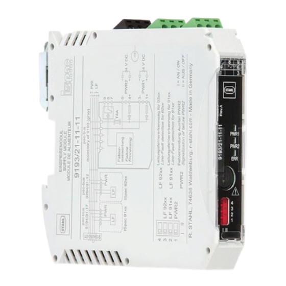
Anhang B Anhang B 15.1 Geräteaufbau Geräteelement Beschreibung Grüne/schwarze Anschlussklemmen für die Hilfsenergie Klemmen und den Sammelfehlermeldekontakt LED "PWR1", grün Anzeige Hilfsenergie 1 LED "PWR2", grün Anzeige Hilfsenergie 2, redundant LED "ERR", rot Sammelfehlermeldung, siehe Kapitel 8.2 Sicherung Auswechselbare Sicherung DIP-Schalter Auswahl der Fehlermeldungen PWR1... - Page 21 Operating instructions Additional languages r-stahl.com Supply Module Type 9193/21-11-11...
- Page 22 Contents General Information ....................3 Manufacturer .......................3 About these Operating Instructions ..............3 Further Documents .....................3 Conformity with Standards and Regulations ............3 Explanation of the Symbols ................4 Symbols in these Operating Instructions ............4 Symbols on the Device ..................4 Safety ........................5 Intended Use .......................5 Personnel Qualification ..................5 Residual Risks ....................6 Transport and Storage ..................7...
-
Page 23: En En
They are legally binding in all legal affairs. Further Documents • Cabinet installation guide • Data sheet For documents in further languages, see r-stahl.com. Conformity with Standards and Regulations • Declaration of Conformity: r-stahl.com. • The device has IECEx approval. See IECEx homepage: http://iecex.iec.ch/ to view the certificate. -
Page 24: Explanation Of The Symbols
Explanation of the Symbols Explanation of the Symbols Symbols in these Operating Instructions Symbol Meaning Tip for making work easier DANGER! Dangerous situation which can result in fatal or severe injuries causing permanent damage if the safety measures are not complied with. -
Page 25: Safety
Specialists who perform these tasks must have a level of knowledge that meets applicable national standards and regulations. Additional knowledge is required for tasks in hazardous areas! R. STAHL recommends having a level of knowledge equal to that described in the following standards: •... -
Page 26: 3.3 Residual Risks
(see the "Technical data" chapter). Do not place any load on the device. Check the packaging and the device for damage. Report any damage to R. STAHL immediately. Do not commission a damaged device. Store the device in its original packaging in a dry place (with no condensation), and make sure that it is stable and protected against the effects of vibrations and knocks. -
Page 27: 4 Transport And Storage
Transport and Storage Improper mounting, installation, commissioning, maintenance or cleaning Basic work such as installation, commissioning, maintenance or cleaning of the device must be performed only in accordance with the valid national regulations of the country of use and only by qualified persons. Otherwise the explosion protection can be rendered ineffective. This may result in explosions causing serious or even fatal injury to persons in the vicinity. -
Page 28: Product Selection And Project Engineering
Product Selection and Project Engineering Product Selection and Project Engineering Calculation of the maximum Number of ISpac Devices per pac-Bus Segment The maximum current carrying capacity of a pac-Bus segment is 4 A. When planning a pac-Bus segment, ensure that the sum of the nominal currents of all ISpac devices does not exceed the value of 4 A. -
Page 29: Mounting And Installation
Mounting and Installation Mounting and Installation Mounting / Dismounting Mount the device carefully and only in accordance with the safety notes (see Chapter "Safety"). Read through the following installation conditions and assembly instructions carefully and follow them precisely. 6.1.1 Operating Position The pac-Bus and the supply module can be installed in any position. - Page 30 Mounting and Installation 6.1.3 Mounting / Dismounting of the Device on DIN Rail and pac-Bus Mounting 15554E00 The pac-Bus is equipped with a polarisation guide and the device with a matching polarisation slot. Position the device as shown in the illustration. Position the cut-out of the enclosure on the outside edge of the DIN rail.
-
Page 31: Installation
Parameterization and Commissioning Installation Operation under difficult conditions, in particular on ships, requires additional measures to be taken for correct installation, depending on the operating location. Further information and instructions on this can be obtained from your regional sales contact upon request. 6.2.1 Electrical Connections / Schematic Diagram See device labelling. -
Page 32: Operation
Operation Operation Operation For device operation, observe the information in the "Intended Use" and "Parameterisation and Commissioning" chapters. In normal operation, the supply module evaluates the error messages of all devices installed on the pac-Bus (prerequisite: the respective ISpac device has an LFD function). These error messages are merged into a collective error message with the statuses of PWR1, PWR2 and the interchangeable fuse using a relay contact and LED signalling. - Page 33 If the error cannot be eliminated using the specified procedures: Contact R. STAHL Schaltgeräte GmbH. For rapid processing, have the following information ready: • Type and serial number of the device • Purchase information •...
-
Page 34: Maintenance, Overhaul, Repair
DANGER! Explosion hazard due to use of a fuse that is not the original fuse! Non-compliance may result in serious or even fatal injury. Use only original accessories and spare parts with the article number 111412 from R. STAHL Schaltgeräte GmbH (see data sheet). Dismounting and replacement of the fuse 20303E00 ... - Page 35 Maintenance, Overhaul, Repair 20305E00 Pull the fuse holder with the fuse out of the enclosure (3). 20306E00 Touch the fuse only with clean gloves to avoid contaminating it. Pull the defective fuse out of the fuse holder (4). ...
-
Page 36: Repair
Only return or package the devices after consulting R. STAHL! Contact the responsible representative from R. STAHL. R. STAHL's customer service is available to handle returns if repair or service is required. Contact customer service personally. Go to the r-stahl.com website. -
Page 37: Cleaning
Accessories and Spare Parts NOTICE! Malfunction or damage to the device due to the use of non-original components. Non-compliance can result in material damage. Use only original accessories and spare parts from R. STAHL Schaltgeräte GmbH (see data sheet). 169070 / 9193603310 Supply Module 2019-07-16·BA00·III·en·01... -
Page 38: Annex A
Annex A Annex A 14.1 Technical Data Explosion Protection Global (IECEx) IECEx BVS 10.0042X Ex ec nC IIC T4 Gc Europe (ATEX) BVS 03 ATEX E 213 X E II 3 G Ex ec nC IIC T4 Gc Certifications and certificates Certificates IECEx, ATEX Further parameters... - Page 39 110 g Mounting type on DIN rail (NS35/15, NS35/7.5) Mounting orientation horizontal or vertical Enclosure IP30 Terminals IP20 Enclosure material PA 6.6 Fire resistance (UL 94) For further technical data, see r-stahl.com. 169070 / 9193603310 Supply Module 2019-07-16·BA00·III·en·01 Type 9193/21-11-11...
-
Page 40: 15.1 Device Design
Annex B Annex B 15.1 Device Design Device component Description Green/black Connection terminals for the auxiliary terminals power and the collective error message contact "PWR1" LED, green Auxiliary power 1 indication "PWR2" LED, green Auxiliary power 2 indication, redundant "ERR" LED, red Collective error message, see Chapter 8.2 Fuse...
Need help?
Do you have a question about the ISpac 9193/21-11-11 and is the answer not in the manual?
Questions and answers