Table of Contents
Advertisement
Available languages
Available languages
Quick Links
Download this manual
See also:
Manual
Advertisement
Chapters
Table of Contents

Related Manuals for Stahl IS1+


Summary of Contents for Stahl IS1+
- Page 1 Betriebsanleitung Operating instructions Additional languages www.r-stahl.com DE EN IS1+ Power Modul für Zone 2 IS1+ power module for zone 2 Reihe 9445/35 Series 9445/35...
- Page 3 Betriebsanleitung Additional languages www.r-stahl.com IS1+ Power Modul für Zone 2 Reihe 9445/35...
-
Page 4: Table Of Contents
Inhaltsverzeichnis Allgemeine Angaben ...................3 Hersteller ......................3 Zu dieser Betriebsanleitung ................3 Weitere Dokumente ....................3 Konformität zu Normen und Bestimmungen ............3 Erläuterung der Symbole ..................4 Symbole in der Betriebsanleitung ...............4 Symbole am Gerät ....................4 Sicherheit ......................5 Bestimmungsgemäße Verwendung ..............5 Qualifikation des Personals ................5 Restrisiken ......................6 Transport und Lagerung ..................8 Produktauswahl, Projektierung und Modifikation ..........8... -
Page 5: De De De
Betriebsanleitung während der Lebensdauer des Geräts aufbewahren. Betriebsanleitung dem Bedien- und Wartungspersonal jederzeit zugänglich machen. Betriebsanleitung an jeden folgenden Besitzer oder Benutzer des Geräts weitergeben. Betriebsanleitung bei jeder von R. STAHL erhaltenen Ergänzung aktualisieren. ID-Nr.: 264697 / 944560310010 Publikationsnummer: 2017-12-08·BA00·III·de·00... -
Page 6: Erläuterung Der Symbole
Erläuterung der Symbole Erläuterung der Symbole Symbole in der Betriebsanleitung Symbol Bedeutung Hinweis zum leichteren Arbeiten GEFAHR! Gefahrensituation, die bei Nichtbeachtung der Sicherheitsmaßnahmen zum Tod oder zu schweren Verletzungen mit bleibenden Schäden führen kann. WARNUNG! Gefahrensituation, die bei Nichtbeachtung der Sicherheitsmaßnahmen zu schweren Verletzungen führen kann. -
Page 7: Sicherheit
Normen und Bestimmungen umfasst. Für Tätigkeiten in explosionsgefährdeten Bereichen sind weitere Kenntnisse erforderlich! R. STAHL empfiehlt einen Kenntnisstand, der in folgenden Normen beschrieben wird: • IEC/EN 60079-14 (Projektierung, Auswahl und Errichtung elektrischer Anlagen) • IEC/EN 60079-17 (Prüfung und Instandhaltung elektrischer Anlagen) •... -
Page 8: De 3.3 Restrisiken
Umgebungsbedingungen (siehe Kapitel "Technische Daten") berücksichtigen. Gerät nicht belasten. Verpackung und Gerät auf Beschädigung prüfen. Beschädigungen umgehend an R. STAHL melden. Beschädigtes Gerät nicht in Betrieb nehmen. Gerät in Originalverpackung, trocken (keine Betauung), in stabiler Lage und sicher vor Erschütterungen lagern. - Page 9 Nur kompatible Komponenten anschließen (Remote I/O-System IS1+/IS1). Im Zweifelsfall Rücksprache mit R. STAHL halten. Reparaturen am Gerät nur durch R. STAHL durchführen lassen. Gerät nur mit feuchtem Tuch und ohne kratzende, scheuernde oder aggressive Reinigungsmittel oder Lösungen schonend reinigen.
-
Page 10: De Transport Und Lagerung
Transport und Lagerung 3.3.2 Beschädigung elektrischer Komponenten Empfindliche elektronische Bauteile können durch elektrostatische Entladung (ESD) beschädigt werden. Vor dem Kontakt mit dem Gerät an einem geerdeten metallischen Körper entladen. Direkte Berührung von Steckverbindern oder Kontakten der Modulsteckplätze vermeiden. ... -
Page 11: Redundanz
Montage und Installation Redundanz Das IS1+ Remote I/O-System kann je nach Applikation auch redundant ausgeführt werden. Dabei wird zwischen CPU-, Power- und System-/Vollredundanz unterschieden. Auswahl des geeigneten Sockels 9496/35 und die maximale Bestückung der CPU Module 9442/35 und Power Module 9445/35 beachten! Folgende Tabelle zeigt die benötigten Komponenten für die jeweiligen Redundanzkonzepte: Sockel 9496/35 CPU Modul 9442/35... -
Page 12: De De
Montage und Installation 6.1.2 Montage auf Sockel 9496/35 GEFAHR! Explosionsgefahr durch unzureichende Befestigung! Nichtbeachten führt zu tödlichen oder schweren Verletzungen. Power Modul mit Sicherungsschrauben befestigen, dazu einen Schraubendreher (Innensechsrund T20) verwenden. 20016E00 Sockel montieren (siehe Betriebsanleitung 9496/35). Power Modul unten an den Sockel einhängen (1) und einschwenken (2). ... - Page 13 Montage und Installation 6.2.2 Upgrade der IS1 PROFIBUS CPM Reihe 9440/15 auf die IS1+ Kommunikationsbaugruppe CPU 9442/35 + Power Modul 9445/35 + Sockel 9496/35 Stromversorgung der IS1 Remote I/O-Station (CPM 9440/15) abschalten. Anschlussleitungen für Kommunikation trennen. Blauen Rasthebel der CPM 9440/15 nach oben ziehen, um Modul zu entriegeln. ...
-
Page 14: Installation
Parametrierung und Inbetriebnahme Installation Bei Betrieb unter erschwerten Bedingungen wie insbesondere auf Schiffen sind zusätzliche Maßnahmen zur korrekten Installation je nach Einsatzort zu treffen. Weitere Informationen und Anweisungen hierzu erhalten Sie gerne auf Anfrage von Ihrem zuständigen Vertriebskontakt. 6.3.1 Hilfsenergie anschließen ... -
Page 15: Betrieb
Betrieb Betrieb Betrieb Zum Betrieb des Geräts die Informationen im Kapitel "Bestimmungsgemäße Verwendung" und "Parametrierung und Inbetriebnahme" beachten. Anzeigen Entsprechende LEDs am Gerät zeigen den Betriebszustand des Geräts an (siehe auch Kapitel "Bestimmungsgemäße Verwendung" und "Geräteaufbau"). Farbe Bedeutung PWR IN grün Betriebsanzeige Hilfsenergie blau... - Page 16 Betrieb Fehler Status Fehlerursache Fehlerbehebung LED "M/S" Außerhalb • Umgebungs- • Umgebungs- blinkt Spezifikation temperatur temperatur außerhalb der verringern durch Spezifikation z.B.: Beschattung • Power Modul oder Kühlung überlastet Hinweis: • Software-Update Ohne Behebung wird das Modul dauerhaft geschädigt • Strombelastung des Power Moduls überprüfen und bei Bedarf senken...
-
Page 17: Instandhaltung, Wartung, Reparatur
Ausfallwahrscheinlichkeit an (siehe Kapitel "Anzeigen" und "Fehlerbeseitigung"). Gerät gemäß den geltenden nationalen Bestimmungen und den Sicherheitshinweisen dieser Betriebsanleitung (Kapitel "Sicherheit") warten. Reparatur Reparaturen am Gerät nur durch R. STAHL durchführen lassen. 264697 / 944560310010 IS1+ Power Modul für Zone 2 2017-12-08·BA00·III·de·00... -
Page 18: Rücksendung
Rücksendung Rücksendung Rücksendung bzw. Verpackung der Geräte nur in Absprache mit R. STAHL durchführen! Dazu mit der zuständigen Vertretung von R. STAHL Kontakt aufnehmen. Für die Rücksendung im Reparatur- bzw. Servicefall steht der Kundenservice von R. STAHL zur Verfügung. -
Page 19: Anhang A
Anhang A Anhang A 14.1 Technische Daten Explosionsschutz Global (IECEx) IECEx PTB 17.0042 X Ex ec [ia Ga, ib Gb] IIC T4 Gc Europa (ATEX) PTB 17 ATEX 2026 X E II 3 (1,2) G Ex ec [ia Ga, ib Gb] IIC T4 Gc Bescheinigungen und Zulassungen Bescheinigungen IECEx, ATEX... - Page 20 Anhang A Technische Daten Galvanische Trennung Prüfspannung gemäß Norm EN 60079-11 zwischen 1500 V AC Hilfsenergie und BusRail / CPU / Sockel Elektromagnetische Geprüft nach folgenden Normen und Vorschriften: Verträglichkeit EN 61326-1 (2013) IEC 61000-4-1...6, NAMUR NE 21 Elektrischer Anschluss Anschluss der 2-polig über steckbare Klemme mit Aderleitung 3 m Hilfsenergie...
- Page 21 Montageart Power Modul 9445/35 nur auf den Sockel 9496/35 aufstecken Einbaulage waagrecht oder senkrecht (Betriebsanleitung des Sockels 9496/35 beachten) Ausführung Schrauben Torx 20 Weitere technische Daten, siehe www.r-stahl.com. 264697 / 944560310010 IS1+ Power Modul für Zone 2 2017-12-08·BA00·III·de·00 Reihe 9445/35...
-
Page 22: Anhang B
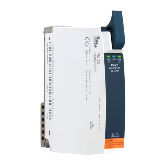
Anhang B Anhang B 15.1 Maßangaben / Befestigungsmaße Maßzeichnungen (alle Maße in mm [Zoll]) – Änderungen vorbehalten 170 [6,69] 155 [6,10] 19757E00 Power Modul 9445/35 18 [7, 66 6,54 67 6,57 19756E00 Power Modul 9445/35 mit Sockel 9496/35 IS1+ Power Modul für Zone 2 264697 / 944560310010 Reihe 9445/35 2017-12-08·BA00·III·de·00... - Page 23 Anhang B 15.1.1 Geräteaufbau Gerätelement Beschreibung Sicherungs- Sicherungsschrauben schrauben für mechanischen Steckverbinder Sicherungs- Innensechsrund- schraube Schraube Größe T20 zum Befestigen am Sockel Anschluss- Mechanische stelle für Steckverbinder mit Steck- Sicherungsschrauben verbinder der und Aderleitungen Hilfsenergie 20020E00 LEDs LEDs zur Status- bzw.
- Page 25 Operating instructions Additional languages www.r-stahl.com IS1+ power module for zone 2 Series 9445/35...
- Page 26 Contents General Information ....................3 Manufacturer .......................3 About these Operating Instructions ..............3 Further Documents .....................3 Conformity with Standards and Regulations ............3 Explanation of the Symbols ................4 Symbols in these Operating Instructions ............4 Symbols on the Device ..................4 Safety ........................5 Intended Use .......................5 Personnel Qualification ..................5 Residual Risks ....................6 Transport and Storage ..................8...
-
Page 27: En En En
For documents in additional languages, see www.r-stahl.com. Conformity with Standards and Regulations • Certificates and EU Declaration of Conformity: www.r-stahl.com. • The device has IECEx approval. See IECEx homepage: http://iecex.iec.ch/ • Further national certificates can be downloaded via the following link: https://r-stahl.com/en/global/products/support/downloads/. -
Page 28: Explanation Of The Symbols
Explanation of the Symbols Explanation of the Symbols Symbols in these Operating Instructions Symbol Meaning Tip for making work easier DANGER! Dangerous situation which can result in fatal or severe injuries causing permanent damage if the safety measures are not complied with. -
Page 29: Safety
Specialists who perform these tasks must have a level of knowledge that meets applicable national standards and regulations. Additional knowledge is required for tasks in hazardous areas! R. STAHL recommends having a level of knowledge equal to that described in the following standards: •... -
Page 30: En 3.3 Residual Risks
(see the "Technical data" chapter). Do not place any load on the device. Check the packaging and the device for damage. Report any damage to R. STAHL immediately. Do not commission a damaged device. Store the device in its original packaging in a dry place (with no condensation), and make sure that it is stable and protected against the effects of vibrations and knocks. - Page 31 Only connect compatible components (IS1+/IS1 Remote I/O system). When in doubt, consult with R. STAHL. Repair work on the device must be performed only by R. STAHL. Gently clean the device only with a damp cloth and without scratching, abrasive or corrosive cleaning agents or solutions.
-
Page 32: En 4 Transport And Storage
Transport and Storage 3.3.2 Damage to Electrical Components Sensitive electronic components can be damaged by electrostatic discharge (ESD). Before making contact with the device, discharge the charge to an earthed metal body. Avoid direct contact with connectors or the contacts on the module slots. ... -
Page 33: En 6 Mounting And Installation
Mounting and Installation Redundancy The IS1+ Remote I/O-System can be redundantly designed based on the application. Here, a distinction is made between CPU redundancy, power redundancy and system redundancy/full redundancy. Comply with the specifications for selecting the suitable 9496/35 base and maximum equipping of the 9442/35 CPU modules and 9445/35 power modules! The following table shows the components required for the respective redundancy concepts: 9496/35 base... -
Page 34: En En
Mounting and Installation 6.1.2 Mounting on the 9496/35 Base DANGER! Explosion hazard due to insecure mounting! Non-compliance may result in serious or even fatal injury. Use the safety screws to fasten the power module. Use a screwdriver (T20 hexalobular internal screws) to do so. 20016E00 ... - Page 35 Mounting and Installation 6.2.2 Upgrade of the Series 9440/15 IS1 PROFIBUS CPM on the IS1+ 9442/35 Communication Assembly CPU + 9445/35 Power Module + 9496/35 Base Switch off the power supply to the IS1 Remote I/O Station (9440/15 CPM). ...
-
Page 36: Installation
Parameterization and Commissioning Installation Operation under difficult conditions, in particular on ships, requires additional measures to be taken for correct installation, depending on the operating location. Further information and instructions on this can be obtained from your regional sales contact upon request. 6.3.1 Connection of the Auxiliary Power ... - Page 37 Operation Operation Operation For device operation, observe the information in the "Intended Use" and "Parameterisation and Commissioning" chapters. Indications The corresponding LEDs on the device indicate the operating state of the device (see also the "Intended Use" and "Device Design" chapters). Colour Meaning PWR IN green Auxiliary power operation indication...
-
Page 38: En Operation
Operation Error Status Cause of error Troubleshooting "M/S" LED Outside the • Ambient temperature • Reduce ambient is flashing specification is outside the temperature, specification for example, • Power module by means of overloaded shading or cooling • Software update Note: If the problem is not eliminated,... -
Page 39: Maintenance, Overhaul, Repair
Perform maintenance on the device according to the applicable national regulations and the safety notes in these operating instructions ("Safety" section). Repair Repair work on the device must be performed only by R. STAHL. 264697 / 944560310010 IS1+ power module for zone 2 2017-12-08·BA00·III·en·00... -
Page 40: Returning The Device
Only return or package the devices after consulting R. STAHL! Contact the responsible representative from R. STAHL. R. STAHL's customer service is available to handle returns if repair or service is required. Contact customer service personally. Go to the www.r-stahl.com website. -
Page 41: Annex A
Annex A Annex A 14.1 Technical Data Explosion Protection Global (IECEx) IECEx PTB 17.0042 X Ex ec [ia Ga, ib Gb] IIC T4 Gc Europe (ATEX) PTB 17 ATEX 2026 X E II 3 (1,2) G Ex ec [ia Ga, ib Gb] IIC T4 Gc Certifications and certificates Certificates IECEx, ATEX... - Page 42 Annex A Technical Data Galvanic separation Test voltage acc. to standard EN 60079-11 Between the 1500 V AC auxiliary power and BusRail / CPU / base Electromagnetic Tested to the following standards and regulations: compatibility EN 61326-1 (2013) IEC 61000-4-1 to 61000-4-6, NAMUR NE 21 Electrical connection Connection of 2-pole via a pluggable terminal with a 3 m single core...
- Page 43 Only connect the 9445/35 power module to the 9496/35 base Mounting position Horizontal or vertical (observe operating instructions for the 9496/35 base) Screw version Torx 20 For further technical data, see www.r-stahl.com. 264697 / 944560310010 IS1+ power module for zone 2 2017-12-08·BA00·III·en·00 Series 9445/35...
-
Page 44: Annex B
Annex B Annex B 15.1 Dimensions / Fastening Dimensions Dimensional drawings (all dimensions in mm [inches]) – Subject to modification 170 [6,69] 155 [6,10] 19757E00 9445/35 power module 18 [7, 66 6,54 67 6,57 19756E00 9445/35 power module with 9496/35 base IS1+ power module for zone 2 264697 / 944560310010 Series 9445/35... - Page 45 Annex B 15.1.1 Device Design Device Description component Safety screws Safety screws for mechanical plug connectors Safety screw Hexalobular internal screw (size T20) for fastening components to the base Connection Mechanical plug point for plug connector with safety connector of screws and single auxiliary power cores...
Need help?
Do you have a question about the IS1+ and is the answer not in the manual?
Questions and answers