Table of Contents
Advertisement
Quick Links
Advertisement
Table of Contents

Related Manuals for Kramer K-Able Box


Summary of Contents for Kramer K-Able Box
- Page 1 Kramer Electronics, Ltd. USER MANUAL Model: K-Able Box Cable Retractor...
-
Page 2: Table Of Contents
Technical Specifications Figures Figure 1: K-Able Box Figure 2: Mounting the K-Able Box and Cable Exit Bracket Horizontally Figure 3: Cable Exit Bracket Showing the Plastic Friction Bush in Place Figure 4: Various Vertical Mounting Options Figure 5: Mounting a Single K-Able Box Vertically... -
Page 3: Introduction
Our 1,000-plus different models now appear in 11 groups that are clearly defined by function. Congratulations on purchasing your Kramer K-Able Box™, which is ideal for boardrooms, conference and training rooms. The package includes the following items: • K-Able Box •... -
Page 4: Quick Start
Getting Started 2.1 Quick Start This quick start chart summarizes the basic steps when installing a K-Able Box. KRAMER: SIMPLE CREATIVE TECHNOLOGY... -
Page 5: Tbus Compatibility
Overview 2.2 TBUS Compatibility The K-Able Box can be used in conjunction with the following Kramer table mount units (when a WCP, WCP-2 or WCP-21 is installed): • TBUS-1A • TBUS-3 • TBUS-4 • TBUS-5 • TBUS-6 • TBUS-9 • TBUS-10... -
Page 6: Component Identification
Overview 3.1 Component Identification Table 1 lists the components supplied with the K-Able Box and their descriptions. Table 1: K-Able Box Component Identification Item Description K-Able Box K-Able Box 60 x 4mm horizontal mounting countersunk head screws Cable exit bracket... -
Page 7: Defining The K-Able Box
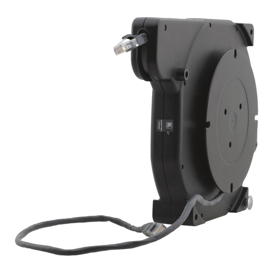
Defining the K-Able Box Defining the K-Able Box Figure 1 Table 2 define the K-Able Box unit. Figure 1: K-Able Box Table 2: K-Able Box Features Feature Function Cable—Fixed End Connect to room wiring infrastructure, for example, leading to a projector... -
Page 8: Mounting The K-Able Box
Figure 2: Mounting the K-Able Box and Cable Exit Bracket Horizontally To mount the K-Able Box horizontally as illustrated in the example in Figure Position the K-Able Box relative to the edge of the table as shown in Figure 2 and secure it using the four wood screws supplied. -
Page 9: Mounting A Single K-Able Box Vertically
Mounting the K-Able Box Figure 3: Cable Exit Bracket Showing the Plastic Friction Bush in Place 5.2 Mounting a Single K-Able Box Vertically Figure 4 shows various vertical mounting options of one or two K-Able Box units. Figure 4: Various Vertical Mounting Options... -
Page 10: Figure 5: Mounting A Single K-Able Box Vertically
Mounting the K-Able Box shows a single K-Able Box mounted vertically next to a TBUS unit. Figure 5 Figure 5: Mounting a Single K-Able Box Vertically shows the vertical mount bracket for a single K-Able Box. Figure 6 Figure 6: Vertical Mount Bracket... -
Page 11: Figure 7: Inserting The Pin And Bolt Into The Bracket
Screw the nut onto the bolt only until the end of the bolt is flush with the nut. Slide the pin at the front of the K-Able Box housing into the front of the vertical mounting bracket at the same time as hooking the bolt onto... -
Page 12: Mounting Multiple K-Able Box Units Vertically
Secure the multiple-mounting bracket to the underneath of the table using the wood screws supplied. Slide the pin through the top mounting hole of each of the K-Able Box units to be mounted. Slide the bolt through the top rear mounting holes of the K-Able Box units. -
Page 13: Figure 9: Mounting Multiple K-Able Box Units Vertically-Rear View
Screw the nut onto the bolt only until the end of the bolt is flush with the nut. Slide the pin at the front of the K-Able Box housings into the front of the multiple-mounting bracket at the same time as hooking the bolt onto the rear of the vertical-mounting bracket. -
Page 14: Using The K-Able Box
Wind the fixed end of the cable around the external spool for storage. Connecting the K-Able Box To connect the K-Able Box: Connect the fixed cable end to the cable infrastructure of the room (for example, leading to a projector). -
Page 15: Technical Specifications
Technical Specifications Technical Specifications Table 4 lists the technical specifications of the K-Able Box. Table 4: Technical Specifications of the K-Able Box DIMENSIONS: 26.7cm x 21.1cm x 3.7cm (10.5" x 8.3" x 1.5") WEIGHT: 1.4kg (3.1lbs) approx. FIXED END CABLE 1m (3.3ft) - Page 16 1. Any product which is not distributed by us or which is not purchased from an authorized Kramer dealer. If you are uncertain as to whether a dealer is authorized, please contact Kramer at one of the agents listed in the Web site www.kramerelectronics.com.
- Page 17 For the latest information on our products and a list of Kramer distributors visit www.kramerelectronics.com where updates to this user manual may be found. We welcome your questions, comments and feedback. Safety Warning: Disconnect the unit from the power supply before opening/servicing.
Need help?
Do you have a question about the K-Able Box and is the answer not in the manual?
Questions and answers