Advertisement
Quick Links
Scan to see website
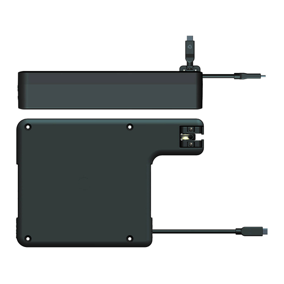
Step 1: Check What's in the Box
The color of the sheet metal box, locking device, and magnet frame are supplied in
the same color as selected for the TBUS.
T-REC5 Cable Retractor HDMI
or USBC F/F (dependent on ordered product)
Step 2: Prepare the Installation Environment
Use this procedure to mount the T-REC5 with the following Kramer TBUS series: T-IN-REC1; T-IN-REC2; T-IN-RND1;
T-IN- RND2. Before mounting the
At least 1 MCP-1 or MCP-2 module is required. The T-REC5 can be positioned in 2 ways - Side-A up or side-B up. Refer to
Step 4: Multiple Retractors.
1.
Choose which
side to
position.
2.
Connect the
bracket
according to
the graphic
marks – Each
side has its
own marked
holes.
T-Rec5 is
designed to be
installed
horizontally. It is
possible to install
vertically as well;
Metal bracket for
vertical placement
must be ordered
separately.
T-REC5-U32/FF, T-REC5-HDMI Quick
Start
T-REC5-U32/FF, T-REC5-HDMI
Quick Start Guide
This guide helps you install and use your T-REC5-U32/FF, T-REC5-HDMI for the first time.
Go to
www.kramerav.com/downloads/T-REC5,
firmware upgrades are available.
Metal bracket
for horizontal
placements
T-REC5
next to the TBUS, you need to mount the TBUS into the table, slide all modules.
Side A Up
to download the latest user manual and check if
4 M5x10mm
screws
P/N:
2900- 301781QS
Side B Up
Rev:
1
Advertisement

Related Manuals for Kramer T-REC5-U32/FF


Summary of Contents for Kramer T-REC5-U32/FF
- Page 1 USBC F/F (dependent on ordered product) placements Step 2: Prepare the Installation Environment Use this procedure to mount the T-REC5 with the following Kramer TBUS series: T-IN-REC1; T-IN-REC2; T-IN-RND1; T-REC5 T-IN- RND2. Before mounting the next to the TBUS, you need to mount the TBUS into the table, slide all modules.
- Page 2 Step 2.1 Retractor Cable Pass-Through for T-IN-REC1 and T-IN-REC2 Series Pull out about 1 meter / 3 ft cable from the retractor and place the retractor under the table. Remove the MCP-1 from the TBUS frame and separate its two parts. Pass the cable through the TBUS frame from under the table and lock the cable head with the MCP-1 two parts.
- Page 3 Step 2.2 Retractor Cable Pass-Through for T-IN-RND1 and T-IN-RND2 Series Pull out about 1 meter / 3 ft cable from the retractor and place the retractor under the table. Pass the cable through the TBUS frame from under the table and slide in one of the pass-through holes. Place and lock the round inner frame into its position.
- Page 4 Step 4: Multiple retractors Side-A up, or mirrored: side-B up When using two retractors next to each other, the retractors need to be positioned mirrored to each other Do not position a retractor on the most far side from the M-LOCK Max.
Need help?
Do you have a question about the T-REC5-U32/FF and is the answer not in the manual?
Questions and answers