Table of Contents
Advertisement
Quick Links
Warning
The installation service manual is not intended for ordinary user. Product
maintenance should be done by qualified professional technician. Incorrect
maintenance may cause other danger.
Please cut off the power supply before the maintenance.
If the power cord has hidden fault, please replace it with relevant technical
parameter. (Please refer to the manual for parameter)
Please read the safety warning in the manual carefully before servicing the product.
After the maintenance, detect it according to relevant regulations before using
This service manual includes multiple models. Please refer to the real product
during operation.
- -
Overseas Thin Range Hood
Installation and Service Manual
Customer Service Center
March.29
th
, 2014
Advertisement
Table of Contents

Related Manuals for Midea A24MABOF50


Summary of Contents for Midea A24MABOF50
- Page 1 Overseas Thin Range Hood Installation and Service Manual Warning The installation service manual is not intended for ordinary user. Product maintenance should be done by qualified professional technician. Incorrect maintenance may cause other danger. Please cut off the power supply before the maintenance. ...
-
Page 2: Table Of Contents
Catalogue … … … … … … … … … … … … … … … … … … … … … … 1. P r e c a u t i o n ………………………………… …………… 2. Dimension …………………… ………………………………………………………… 3. -
Page 3: Precaution
1. Precaution Safety Precaution 1、Please follow the following instructions to avoid hurting the user or other property damage. 2、Faulty operation due to neglecting the instructions will caused injury or damage. 3、Please read the following instructions carefully before the maintenance. Warning 1. -
Page 4: Function
MODEL A24MABOF50 597mm 500mm 140mm A30MABOF50 757mm 500mm 140mm 897mm 500mm 140mm A35MABOF50 597mm 500mm 150mm E60MEBOF52 757mm 500mm 150mm E76MEBOF52 897mm 500mm 150mm E90MEBOF52 597mm 500mm 135mm E60MEBOF96 757mm 500mm 135mm E76MEBOF96 897mm 500mm 135mm E90MEBOF96 Note: Dimension data is only for reference. -
Page 5: Circuit Diagram
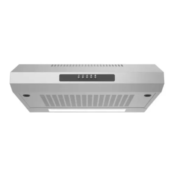
As shown in the picture, press the button indicated by the red arrow, smoke exhaust function of large airflow is on; press the button indicated by the yellow arrow, switched to smoke exhaust function of middle airflow; press the button indicated by the green arrow, switched to smoke exhaust function of small airflow; press the button indicated by the brown arrow, all smoke exhaust functions except lamp are cancelled. -
Page 6: Range Hood Installation
Range Hood Installation Methods 1: as shown in Figure(1), to ensure the thin range hood in the cabinet, wooden plank should be parallel to the four lock holes of thin hood top. Install the four screws in the cabinet according to the relative position of four lock holes and tighten them. - Page 7 Clasp the filter buckle by hand, press down and pull out Check Valve and Fan Cover Mounting and Dismounting Step: as shown in the picture, hold the check valve or fan cover respectively, rotate until the blade rotated to the vacant position from the board, then, the check valve or fan cover can be taken down.
-
Page 8: Dismantle Control Box Assembly
Remove the screw of lamp panel, tilt the right and push out the lamp panel in the Rotate the bulb in the arrow direction, arrow direction take out the bulb Dismantle Control Box Assembly Tool: Cross screwdriver Step 1: twist off the two fixing screws of control box assembly with cross screwdriver, as shown in the picture Step 2: pull out the terminal connecting control box assembly to fan, the control box assembly dismantling is done, as shown in the picture. -
Page 9: Volute Assembly Dismantling
6.5 Volute Assembly Dismantling Tool: Cross screwdriver Step: as the above step, pull out the terminal connecting control box assembly to terminal box, twist off six volute fixing screws on the body top and one grounding screw, take out volute assembly, as shown in the picture. - Page 10 Step: as the above step, pull out the terminal connecting the motor to control box assembly, twist off the four fixing screws of air inlet cover with cross screwdriver, then take out motor impeller assembly, as shown in the picture. Black decoration cover and Motor shaft nut and impeller blade motor fixing nut...
-
Page 11: Dismantle Power Cord
Step 2: open the two black decoration cover on the air inlet cover, unscrew the motor fixing nut with M4 hex nut sleeve, then use M5 hex nut sleeve to unscrew motor shaft nut, take out the impeller, finally, the motor, impeller and air inlet cover dismantling are completed, as shown in the picture. -
Page 12: Lamp Holder Dismantling
6.8 Lamp Holder Dismantling Tool: M14 hex small wrench Step: as the above step, open the terminal box cover, pull out the terminal of lamp holder and control box assembly, loosen the hex nut at the end of lamp holder with M14 hex small wrench, then take out the lam holder and lampshade from the side groove, as shown in the picture. -
Page 13: Main Components Maintenance And Detection
Problem Possible Causes Maintenance Measures 1.Replace the same spec and model spotlight 1.Spotlight is damaged due to aging. 2.Check whether the lamp holder, terminal and the circuit itself have damage, if damaged, doesn’t 1. Spotlight 2.Lamp cord has poor contact or replace the lamp holder;... - Page 14 7.2.2 Motor Replacement Tool: Cross screwdriver, M4 hex nut sleeve and M5 hex nut sleeve. Operation Step: 1.Dismantle the damaged motor according to motor dismantling step in 6.7; 2.Prepare the intact motor for replacement; install the motor according to the contrary step sequence of 6.7.
Need help?
Do you have a question about the A24MABOF50 and is the answer not in the manual?
Questions and answers