DMP Electronics XR550INT Series Installation Manual
International control panel
Hide thumbs
Also See for XR550INT Series:
- Installation manual (26 pages) ,
- Installation manual (4 pages)
Table of Contents
Advertisement
Quick Links
Advertisement
Table of Contents

Related Manuals for DMP Electronics XR550INT Series


Summary of Contents for DMP Electronics XR550INT Series
-
Page 1: Installation Guide
INSTALLATION GUIDE XR150INT/XR550INT SERIES INTERNATIONAL CONTROL PANEL... - Page 2 MODEL XR150INT/XR550INT SERIES PANELS INSTALLATION GUIDE © 2018 Digital Monitoring Products, Inc. Information furnished by DMP is believed to be accurate and reliable. This information is subject to change without notice. Digital Monitoring Products XR150INT/XR550INT Series Installation Guide...
-
Page 3: Table Of Contents
Terminal 9 - GREEN ...................14 Terminal 10 - BLACK ..................14 Programming (PROG) Connection ...............14 Keypad Bus LEDs ....................14 OVC LED(s) .......................14 Smoke and Glassbreak Detector Output Terminals 11 and 12 ...................15 Current Rating ....................15 Digital Monitoring Products XR150INT/XR550INT Series Installation Guide... - Page 4 Phone Line Monitor ....................19 RESET and TAMPER Headers 18.1 RESET Header ....................20 18.2 TAMPER Header ....................20 Cellular Modules 19.1 CELL MODULE Header ..................21 19.2 Module Installation ....................21 19.3 Connecting the Antenna ..................21 International Certifications Digital Monitoring Products XR150INT/XR550INT Series Installation Guide...
-
Page 5: Product Specifications Summary
A Model 431 Output Harness is required to use these outputs. The XR150INT/XR550INT Series panels also provide four open collector outputs rated for 50mA each. The open collector outputs provide ground connection for a positive voltage source. A Model 300 Output Harness is required to use these outputs. -
Page 6: Enclosure Specifications
Panel Features Description The DMP XR150INT/XR550INT Series system is made up of an alarm panel with a built-in communicator, an enclosure, battery, one transformer, and keypads. Each panel is a versatile 12VDC, combined access control, burglary, and fire communicator panel with battery backup. The panels provide eight on-board burglary zones and two on-board 12 VDC Class B powered zones. -
Page 7: Caution Notes
Discharge (ESD) that can damage system components. Compliance Instructions For applications that must conform to a local authorities installation standard or a National Recognized Testing Laboratory certificated system, please see the Compliance Listing Guide LT-1330INT for additional instructions. Digital Monitoring Products XR150INT/XR550INT Series Installation Guide... -
Page 8: System Components
System Components Specific and Non-specific Wired Interconnections The XR150INT/XR550INT Series panels diagram below shows some of the accessory modules you can connect for use in various applications. A brief description of each module follows in section 3.3. Form C Relays (J2) Output Color Code–Model 431 Harness... -
Page 9: Accessory Devices
SYSTEM COMPONENTS Accessory Devices Cellular Communicator Cards 263HINT HSPA+ Cellular Allows you to connect the XR150INT/XR550INT Series panels to any compatible HSPA/SMS network. Communicator Accessory Modules 270 Network Transient Provides transient surge protection for the ETHERNET Connector. Suppression Module Expansion Modules 710 Bus Splitter/Repeater Allows you to increase keypad or LX-Bus™... - Page 10 Graphic Touchscreen keypads to the keypad bus using terminals 7, 8, 9, and 10. Wireless keypads Allows you to control the panel from various remote locations. Connect up to seven 9060-WINT/9063-WINT Wireless Keypads or 9862-WINT/9863-WINT Wireless Graphics Keypads. Digital Monitoring Products XR150INT/XR550INT Series Installation Guide...
-
Page 11: Installation
Installation Mounting the Enclosure The metal enclosure for the XR150INT/XR550INT Series panels must be mounted in a secure, dry place to protect the panel from damage due to tampering or the elements. It is not necessary to remove the panel PCB when installing the enclosure. -
Page 12: Mounting Keypads And Zone Expansion Modules
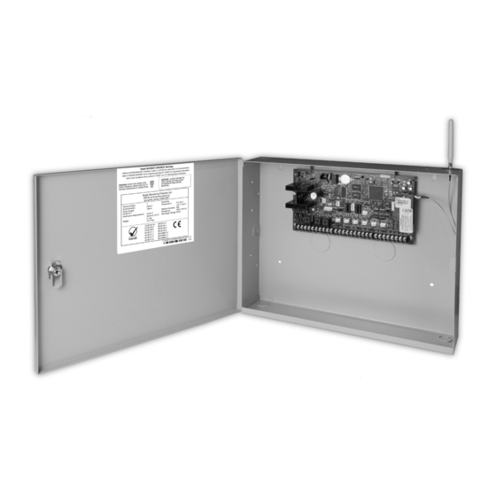
Enclosure Enclosure Figure 3: XR550INT Series in Model 352XINT Enclosure and Separate 352S Enclosure with Shelves Mounting Keypads and Zone Expansion Modules DMP LCD keypads have removable covers that allow you to easily mount the keypad to a wall or other flat surface using the screw holes on each corner of the base. -
Page 13: Connecting Lx-Bus™, Ax-Bus™ And Keypad Bus Devices
LED turns from Red to Green. Wireless keypads are assigned to the Figure 4: XR550INT Series Panel Showing first open device position in Device Setup Reset and Transmit/Receive automatically based upon the order in which they are detected. -
Page 14: Ac Terminals 1 And 2
The leads need a momentary short only. Once the relay has pulled in, the battery voltage holds it in that condition. If the XR150INT/XR550INT Series panel is powered up with an AC transformer, the battery cutoff relay is pulled in automatically. For more information refer to Figure 1. -
Page 15: Battery Supervision
INSTALLATION Battery Supervision The XR150INT/XR550INT Series panels tests the battery when AC power is present. The test is done every three minutes and lasts for five seconds. During the test, the panel places a load on the battery; if the battery voltage falls below 11.2 VDC a low battery is detected. - Page 16 *Based on 10% of active zones in alarm Total Standby______mA x number of Standby Hours needed ______ = _______mA-hours Total Alarm ______mA +_______mA-hours Total _______mA-hours X .001 = _______Amp-hrs Required Refer to section 6.9 for standby battery selection. Digital Monitoring Products XR150INT/XR550INT Series Installation Guide...
-
Page 17: Standby Battery Selection
For listed installations, batteries can be installed in a DMP Model 349, 350 or 352S enclosure and all wiring shall run through conduit. The enclosure shall be installed to the left of the XR150INT/XR550INT Series panel enclosure to ensure Battery and AC wire separation. -
Page 18: Bell Output
Keypad Bus Description XR150INT/XR550INT Series panel terminals 7, 8, 9, and 10 are for the keypad bus. You can connect up to 16 supervised keypads to the XR550INT Series panel and 8 supervised keypads to the XR150INT Series panel as well as multiple unsupervised keypads. In addition to DMP LCD keypads, you can also connect any combination of zone expansion modules to the data bus up to a total of 16 devices. -
Page 19: Smoke And Glassbreak Detector Output
Protection Zones 10.1 Terminals 13–24 Zones 1 to 8 (terminals 13 to 24) on the XR150INT/XR550INT Series panel are all grounded burglary zones. For programming purposes, the zone numbers are 1 through 8. Listed below are terminal 13 to 24 connection functions. -
Page 20: Zone Response Time
Dry Contact Relay Outputs 12.1 Description The XR150INT/XR550INT Series panel provides two programmable auxiliary SPDT relays when equipped with two DMP Model 305 relays in sockets OUTPUT 1 and OUTPUT 2 and a Model 431 Output Harness on the OUT1-OUT2 6-pin Header. Each relay provides one SPDT set of contacts that can be operated by any of the... -
Page 21: Model 431 Output Harness Wiring
Black 13.3 Model 860 Relay Module Connect a Model 860 Relay Module to the OUTPUTS header on the XR150INT/XR550INT Series panel to provide relays for outputs 3-6. Use these relays for electrical isolation between the alarm panel and other systems or for switching voltage to control various functions. -
Page 22: Lx-Bus Tm Tm
Expansion 15.1 LX-Bus HeadersLX-Bus/AX-Bus Headers XR150INT/XR550INT Series panels are capable of providing zone, output, and access control expansion by connecting hardware modules to the AX/LX-Bus headers on the control panel. XR150INT panels are manufactured with one LX-Bus header labeled LX500. AX-Bus operation does not apply to XR150INT panels. -
Page 23: Ovc Leds
PHONE LINE connector and the RJ31X or RJ38X phone block. The maximum impedance is 100 Ohms. 17.2 Phone Line Monitor The XR150INT/XR550INT Series panel has a built-in telephone monitor that monitors the phone line voltage to verify the connection to the central office. Figure 10 and the table below identify the phone block pin layout, wire numbers, and colors. -
Page 24: Reset And Tamper Headers
The RESET header is located to the left of the Expansion Header (EXP) on the right side of the circuit board and is used to reset the XR150INT/XR550INT Series microprocessor. To reset the panel when first installing the system, install the reset jumper before applying power to the panel. -
Page 25: Cellular Modules
The CELL MODULE header is located to the right of the Expansion (EXP) Module header on the right side of the circuit board and is used to connect the DMP Model 263HINT HSPA+ Cellular Communicators. This provides a fully supervised alarm communication path for the XR150INT/XR550INT Series panel. Refer to the 263HINT (LT-1270INT) Installation Sheet for complete information. -
Page 26: International Certifications
≤16 A per phase and not subject to conditional connection. EN 61000-6-4:2007 Emission standard for industrial environments. Digital Monitoring Products XR150INT/XR550INT Series Installation Guide... - Page 27 Documentation Security Grade: Environmental Class II Power Supply: Type A Power Input 18 VAC, 50 Hz, 400 mA, Class II EN 50131-1 Notification Requirements Grade 3 Options A,B, or C Weight: 6.1 kg (13.5 lbs) Environmental Class: Operating Temperature: 0°C - 49°C (32°F - 120°F) Relative Humidity: Dimensions: 26W x 14H cm...
Need help?
Do you have a question about the XR550INT Series and is the answer not in the manual?
Questions and answers