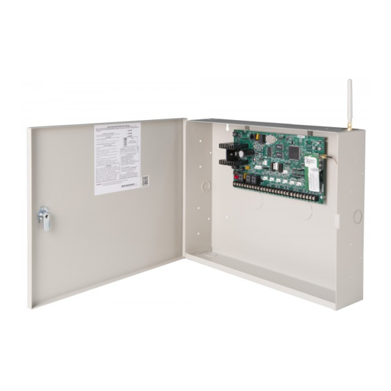
DMP Electronics XR550 Series Testing Manual
Hide thumbs
Also See for XR550 Series:
- Installation manual (26 pages) ,
- User manual (88 pages) ,
- Troubleshooting manual (40 pages)
Table of Contents
Advertisement
Quick Links
XR550 Series System
Post-Installation Testing ................................. 2
Test Communication ............................................................ 2
Test Cellular Signal Strength .............................................. 3
Test Hardwired and Wireless Zones .................................. 3
Test Key Fobs ....................................................................... 4
Test Panel Batteries ............................................................. 4
Troubleshooting Testing................................. 5
Perform a Walk Test ............................................................. 5
Use the Diagnostics Function ............................................ 7
LT-1687 17333
Testing Guide
TABLE OF CONTENTS
Test the LX-Bus ............................................................................. 7
Check the Zone State .................................................................. 7
Retrieve the LX-Bus Status ........................................................8
Advertisement
Table of Contents

Subscribe to Our Youtube Channel
Summary of Contents for DMP Electronics XR550 Series
- Page 1 XR550 Series System Testing Guide TABLE OF CONTENTS Post-Installation Testing ......... 2 Test Communication ............2 Test Cellular Signal Strength ..........3 Test Hardwired and Wireless Zones ........3 Test Key Fobs ............... 4 Test Panel Batteries ............. 4 Troubleshooting Testing......... 5 Perform a Walk Test .............
- Page 2 POST-INSTALLATION TESTING After an XR550 Series system has been installed, perform the tests outlined in this section to ensure that each element of the system is functioning properly. Test Communication The panel contains a Diagnostics function that allows you to test the communication integrity of the LX-Bus™, identify individual zones, and display the present electrical state of any zone.
- Page 3 Emergency (EM) • Supervisory (SV) • Fire (FI) The following zones have other specific conditions that require consulting the panel’s programming to be properly tested. • Fire Verify (FV) • Arming (AR) XR550 SERIES SYSTEM TESTING GUIDE DIGITAL MONITORING PRODUCTS...
- Page 4 Individual panel batteries should be tested while they are disconnected from the charging circuit of the panel, and disconnected from an array of multiple batteries. For proper testing, use a battery load tester. Consult the instructions of your battery load tester to determine proper testing procedures. XR550 SERIES SYSTEM TESTING GUIDE DIGITAL MONITORING PRODUCTS...
- Page 5 Includes all wireless devices except key fobs and transmitters programmed for a supervision time of 0 (zero). PIR (Wireless PIR Walk Test) - The PIR Walk Test allows the installer to verify XR550 SERIES SYSTEM TESTING GUIDE DIGITAL MONITORING PRODUCTS...
- Page 6 Walk Test. Faulted zones then display on the keypad. Note: Key fobs do not send failure messages in order to prevent functioning key fobs that are not present at the time of the test from being reported as MISSING. XR550 SERIES SYSTEM TESTING GUIDE DIGITAL MONITORING PRODUCTS...
- Page 7 4. The display changes to ZONE NUMBER:. Enter in the zone number you want to check and press CMD. 5. The panel displays the current state of the zone as NRML (normal), OPEN, or SHORT. XR550 SERIES SYSTEM TESTING GUIDE DIGITAL MONITORING PRODUCTS...
- Page 8 Retrieve the LX-Bus Status This function allows the panel to poll all devices connected to the LX-Bus of an interface card and check for any overlapped, missing, or extra addresses. To retrieve the system’s LX-Bus status using the Diagnostics function, follow these steps: Reset the panel.


Need help?
Do you have a question about the XR550 Series and is the answer not in the manual?
Questions and answers