Table of Contents
Advertisement
Quick Links
Advertisement
Table of Contents

Related Manuals for DMP Electronics XR150CAN Series


Summary of Contents for DMP Electronics XR150CAN Series
- Page 1 INSTALLATION GUIDE XR150/XR550 SERIES CANADIAN CONTROL PANEL...
- Page 2 MODEL XR150CAN/XR550CAN Series CANADIAN INSTALLATION GUIDE INDUSTRY CANADA NOTICE This Class A digital apparatus complies with Canadian ICES-003. © 2018 Digital Monitoring Products, Inc. Information furnished by DMP is believed to be accurate and reliable. This information is subject to change without notice.
-
Page 3: Table Of Contents
TABLE OF CONTENTS Product Specifications Power Supply .................1 Communication ..............1 Panel Zones ................1 Keypad Bus ................1 LX-Bus™ ................1 Outputs .................1 1.7 Enclosure Specifications ............2 Panel Features Description ................2 Zone Expansion ..............2 Output Expansion ..............2 Central Station Communication ..........2 Encrypted Communications (XR550 with Encryption only) ..3 Compliance Instructions ............3 System Components Wiring Diagram ..............4... - Page 4 TABLE OF CONTENTS Smoke and Glassbreak Detector Output Terminals 11 and 12 .............15 Current Rating ..............15 Protection Zones 10.1 Terminals 13–24 ..............15 10.2 Dual EOL ................15 10.3 Zone Response Time .............15 10.4 Keyswitch Arming Zone ............15 Powered Zones for 2-Wire Smoke Detectors 11.1 Terminals 25–26 and 27–28 ..........16 Dry Contact Relay Outputs...
-
Page 5: Product Specifications
INTRODUCTION Product Specifications Power Supply Transformer Input: Model 327CAN, plug-in — Primary input: 120 Vac, 60 Hz, Secondary output: 16.5 Vac 50 VA Model FTA7516 ATC Frost from Standex Electronics — Primary input: 120 Vac, 60 Hz, Secondary output: 16 Vac 75 VA Standby Battery: 12 VDC, 1.0 Amps Max. -
Page 6: Enclosure Specifications
INTRODUCTION Enclosure Specifications The panels are shipped in an enclosure with a transformer, End-of-Line resistors, battery leads, user’s guide, and programming sheets. Enclosure Size Color(s) Construction (Cold Rolled Model Steel) 17.5”W x 13.5”H x 3.5”D Gray (G) or Red (R) 18-Gauge 350A 17.5”W x 13.5”H x 3.75”D... -
Page 7: Encrypted Communications (Xr550 With Encryption Only)
INTRODUCTION Encrypted Communications (XR550 with Encryption only) An XR550 panel with encryption communicates using 128-bit or 256-bit AES encryption. If you currently have an XR550 panel installed, you may contact DMP Customer Service with the panel serial number. The serial number(s) should be sent in writing via e-mail or fax. -
Page 8: System Components
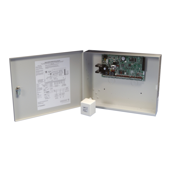
INTRODUCTION System Components Wiring Diagram The XR550 Series diagram below shows some of the accessory modules you can connect for use in various applications. A brief description of each module follows in section 3.3. Front and Rear tamper protection included with Model 350A Attack Resistant Enclosure. -
Page 9: Accessory Devices
INTRODUCTION Accessory Devices Cellular Communicators 263HCAN HSPA+ Canadian Allows you to connect the XR150/XR550 Series to any compatible HSPA/SMS network. Cellular Communicator Accessory Modules 270 Network Transient Provides transient surge protection for the J1 Ethernet Connector. Suppression Module 277CAN Trouble Sounder Provides local sounder for monitoring of panel operations and loss of Keypad Bus. -
Page 10: Accessory Devices (Continued)
INTRODUCTION Accessory Devices (continued) DMP Two-Way Wireless Devices (continued) 1142BC Two-button Hold-up Belt Provides two-button hold-up operation with a belt clip. Clip Transmitter 1142 Two-button Hold-up Provides permanently mounted under-the-counter two-button hold-up operation. Transmitter 1145-4 (Four-Button) Key Fob transmitters designed to clip onto a key ring or lanyard. 1145-2 (Two-Button) 1145-1 (One-Button) 1164 Wireless Synchronized... -
Page 11: Installation
INSTALLATION Installation Mounting the Enclosure The metal enclosure for the XR150/XR550 Series must be mounted in a secure, dry place to protect the panel from damage due to tampering or the elements. It is not necessary to remove the XR150/XR550 Series PCB when installing the enclosure. -
Page 12: Mounting Keypads And Zone Expansion Modules
INSTALLATION 56 VA Transformer Mounting Plate XR550 Panel XR550 Panel Mounting for one (1) Zone Expansion Module. Battery Shelf Figure 4: XR550 Series in Model 352X Enclosure and Separate 352S Enclosure with Shelves Mounting Keypads and Zone Expansion Modules DMP LCD keypads have removable covers that allow you to easily mount the keypad to a wall or other flat surface using the screw holes on each corner of the base. -
Page 13: Connecting Lx-Bus And Keypad Bus Devices
INSTALLATION Connecting LX-Bus and Keypad Bus Devices Connections for LX-Bus and Keypads are provided through the J8 (PROG), J14 (LX500), J9 (LX600), J15 (LX700), J17 (LX800), J19 (LX900), and J13 (XBUS) 4-pin headers. Several factors determine the DMP LX-Bus™ and keypad bus performance characteristics: the wire length and gauge used, the number of devices connected, and the voltage at each device. -
Page 14: Secondary Power Supply
INSTALLATION Secondary Power Supply Battery Terminals 3 and 4 Connect the black battery lead to the negative battery terminal. The negative terminal connects to the enclosure ground internally through the XR150/XR550 Series circuit board. Connect the red battery lead to the battery positive terminal. -
Page 15: Xr150/Xr550 Series Canadian Power Requirements
INSTALLATION XR150/XR550 Series Canadian Power Requirements During AC power failure, the XR150/XR550 Series panel and all connected auxiliary devices draw their power from the battery. All devices must be taken into consideration when calculating the battery standby capacity. The following table lists the XR150/XR550 Series panel power requirements. You must add the additional current draw of keypads, zone expansion modules, smoke detector output, and any other auxiliary devices used in the system for the total current required. - Page 16 INSTALLATION Standby Battery Power Calculations Standby Current Alarm Current 736P POPIT Interface Module Qty _______ 25mA ______ Qty _______ 25mA ______ Radionics Popex, POPITs, OctoPOPITs Qty _______ ___mA ______ Qty _______ ___mA ______ 738A Ademco Wireless Interface Module Qty _______ 75mA ______ Qty _______ 75mA ______...
-
Page 17: Standby Battery Selection
INSTALLATION Standby Battery Selection To choose the type and number of batteries needed for 24, 60, or 72 hours of standby power based on the Amp Hours Required calculation from section 6.8 XR150/XR550 Series Power Requirements, perform the following: 1. Select the desired standby hours required from the table below: 24, 60, or 72 hours. 2. -
Page 18: Bell Output
INSTALLATION Bell Output Terminals 5 and 6 Terminal 5 supplies positive 12VDC to power alarm bells or horns. This output can be steady, pulsed, or temporal depending upon the Bell Action specified in Bell Options. Terminal 6 is the ground reference for the bell circuit. This supervised output detects 1k Ohms or less as normal. -
Page 19: Smoke And Glassbreak Detector Output
INSTALLATION Smoke and Glassbreak Detector Output Terminals 11 and 12 Terminal 11 supplies positive 12VDC Regulated to power 4-wire smoke detectors and other powered devices. This output can be turned off by the user for 5 seconds using the Sensor Reset User Menu option to allow latched devices to reset. -
Page 20: Powered Zones For 2-Wire Smoke Detectors
INSTALLATION Powered Zones for 2-Wire Smoke Detectors 11.1 Terminals 25–26 and 27–28 Panel terminals 25 through 28 provide two resettable Class B, Style A, 2-wire powered zones. For programming purposes the zone numbers are 9 and 10. Note: The maximum wire length for either zone 9 or zone 10 is 3000 feet using 18 AWG or 1000 feet using 22 AWG. -
Page 21: Annunciator Outputs
INSTALLATION Annunciator Outputs 13.1 Description The four programmable annunciator outputs can be programmed to indicate the activity of the panel zones or conditions occurring on the system. Annunciator outputs do not provide a voltage but instead switch-to-ground a voltage from another source. The outputs can respond to any of the conditions listed in the Description section for Dry Contact Relays. -
Page 22: Ovc Leds
INSTALLATION 15.3 OVC LEDs The Overcurrent LED (OVC) lights Red when the devices connected to the Keypad Bus and LX-Bus(es) draw more current than the panel is rated for. The LED(s) turn a steady Red when lit. When the OVC LED(s) light red, the appropriate LX-Bus(es) and Keypad bus are shut down. -
Page 23: Reset And Tamper Headers
INSTALLATION to determine if panel is seizing the line: 1. Unplug phone cord from RJ31X 2. Place butt-set on pins 4 and 5 3. Listen for dial tone. With dial tone present, lift either wire from pins 1 or 8 4. -
Page 24: Lx-Bus™ Module Connection
COMPLIANCE Wiring Diagrams 20.1 LX-Bus™ Module Connection LX-Bus Expansion Each LX-Bus Module must have its own independent address ranging from 00 to 99. A Supervisory zone must be programmed into the panel to properly supervise each module. Yellow Green To additional Black LX-Bus Modules LX-Bus™... -
Page 25: Model 860 Relay Module Connection
WIRING DIAGRAMS 20.2 Model 860 Relay Module Connection Model 860 Relay Module BL K Relay 1 Common Relay 2 4-wire Harness Relay 3 Assembly Relay 4 +12VDC Programmable Relay contact rating: 1 Amp @ 30VDC, Resistive, Power Limited 20.3 Dual Zone Protection Digital Monitoring Products XR150/XR550 Series Canadian Installation Guide... - Page 26 Certifications Meets ANSI/SIA CP-01-2010 False Alarm Reduction. This Class A digital apparatus complies with Canadian ICES-003 Underwriters Laboratory of Canada (ULC) Listed ULC S545 Household Fire ULC C1023 Household Burglar ULC/ORD-C1076 Proprietary Burglar ULC S304 Central Station Burglar ULC S559 Fire Signal Receiving Centres and Systems 800-641-4282 IN TRUSIO N •...
Need help?
Do you have a question about the XR150CAN Series and is the answer not in the manual?
Questions and answers