Table of Contents
Advertisement
Quick Links
Advertisement
Table of Contents

Subscribe to Our Youtube Channel
Related Manuals for DMP Electronics Command Processor XR200


Summary of Contents for DMP Electronics Command Processor XR200
- Page 1 INST ALLA TION GUIDE XR200—242-ZONE COMMAND PROCESSOR™ PANEL...
- Page 2 MODEL XR200 COMMAND PROCESSOR INSTALLATION GUIDE FCC NOTICE This equipment generates and uses radio frequency energy and, if not installed and used properly in strict accordance with the manufacturer’s instructions, may cause interference with radio and television reception. It has been type tested and found to comply with the limits for a Class A computing device in accordance with the specification in Subpart J of Part 15 of FCC Rules, which are designed to provide reasonable protection against such interference in a residential installation.
-
Page 3: Table Of Contents
T ABLE OF CONTENTS Revisions to This Document Product Specifications Power Supply .........1 Communication........1 Panel Zones..........1 Keypad Data Bus ........1 LX-Bus™ ..........1 Outputs..........1 Enclosure Specifications ......1 Panel Features Description ..........2 Expansion Zones........2 Relay Output Expansion ......2 Partitions and Areas ........3 Central Station Communication ....3 Before you Begin ........3 About this Guide ........3... - Page 4 T ABLE OF CONTENTS Smoke and Glassbreak Detector Output Terminals 11 and 12......10 Current Rating ........10 Protection Zones 10.1 Terminals 13–24 ........11 10.2 Operational parameters ......11 10.3 Zone response time ......11 10.4 Keyswitch arming zone......11 Powered Zones for 2-Wire Smoke Detectors 11.1 Terminals 25–26 and 27–28....11 11.2...
- Page 5 T ABLE OF CONTENTS UL 864 NFPA 72 (Chapter 9) Specifications 18.1 Zone Restoral Reports ......17 18.2 Power Fail Delay ........17 18.3 Sprinkler Supervisory ......17 18.4 DACT Systems ........17 18.5 Type 2 and Type 3 Central Station Service ......17 18.6 Type 1 Central Station Service ....17 18.7 Local Protective Signaling Systems ..18...
-
Page 6: Revisions To This Document
REVISIONS Revisions to This Document This section explains the changes that were made to this document during this revision. This section lists the date the change was made, the section number and section heading, and a quick summary of the change. Date Section Number and Heading Quick Explanation of Changes... -
Page 7: Product Specifications
INTRODUCTION Product Specifications Power Supply Transformer Input: 16.5 VAC 40 VA (Models 320 or 321) Standby Battery: 12 VDC 7.7Ah (40 VA charges 2 batteries; 56 VA and 100 VA charges up to 4 batteries) Auxiliary: 12 VDC output at 1 Amp Bell Output: 12 VDC at 1.5 Amp All circuits are inherent Power Limited except the red battery wire. -
Page 8: Panel Features
INTRODUCTION Panel Features Description The DMP XR200 Command Processor™ Panel is a versatile 12 VDC, combined burglary and fire communicator panel with battery backup. The XR200 provides 8 on-board burglary zones and 2 on-board 12 VDC Class B powered zones. The powered zones have a reset capability to provide for 2-wire smoke detectors, relays, or other latching devices. -
Page 9: Partitions And Areas
INTRODUCTION Partitions and Areas The 20 reporting areas of the XR200 are divided into four separate partitions. Partition 1 provides up to eight individual reporting areas while partitions 2, 3, and 4 each provide up to four individual reporting areas. Keypads installed on the XR200 system are assigned to partitions allowing users to operate the functions of those areas. -
Page 10: System Components
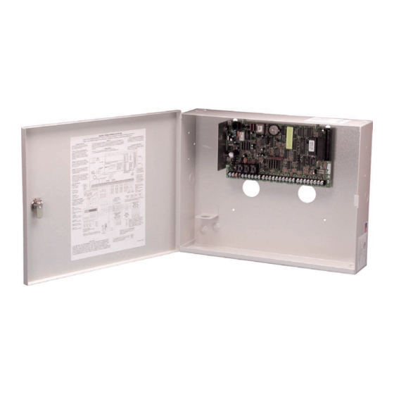
INTRODUCTION System Components Description The DMP XR200 system is made up of an alarm panel with a built-in communicator, an enclosure, battery, one 16.5 VAC transformer, and a keypad. You can add up to eight supervised Security Command® keypads; wireless, network communications, and expansion interface cards; zone and output expander modules; and initiating and indicating circuit modules. -
Page 11: Lightning Protection
INTRODUCTION Lightning Protection Metal Oxide Varistors and Transient Voltage Suppressors help protect against voltage surges on input and output circuits of the XR200. Additional surge protection is available by installing the DMP 370 or 370RJ Lightning Suppressors. Accessory Devices Interface Adaptor and Interface Cards 460 Interface Adaptor Card Allows you to connect two or more expansion interface cards to the XR200 panel. -
Page 12: Installation
INST ALLA TION Installation Mounting the Enclosure The metal enclosure for the XR200 must be mounted in a secure, dry place to protect the panel from damage due to tampering or the elements. It is not necessary to remove the XR200 PC board when installing the enclosure. -
Page 13: Mounting Keypads And Zone Expansion Modules
INST ALLA TION Mounting Keypads and Zone Expansion Modules Security Command® keypads have removable covers that allow you to easily mount the keypad to a wall or other flat surface using the screw holes on each corner of the base. Before mounting the base, connect the keypad wire harness leads to the keypad cable from the panel and to any device wiring run to that location. -
Page 14: Secondary Power Supply
INST ALLA TION Secondary Power Supply Battery Terminals 3 and 4 Connect the black battery lead to the negative terminal of the battery. The negative terminal connects to the enclosure ground internally through the XR200 circuit board. Connect the red battery lead to the positive terminal of the battery. - Page 15 INST ALLA TION Standby Battery Power Calculations Standby Current Alarm Current XR200 Control Panel Qty ______x 80mA ______mA 80mA ______mA Relay Outputs 1-2 (ON) Qty ______x 30mA ______ Qty ______x 30mA ______ Voltage Outputs 3-10 (ON) Qty ______x ______ Qty ______x ______ Active Zones 1-8 Qty ______x...
-
Page 16: Bell Output
INST ALLA TION Bell Output Terminals 5 and 6 Terminal 5 supplies positive 12 VDC to power alarm bells or horns. The output is rated for a maximum output of 1.5 Amps. This output can be steady or pulsed depending upon the Bell Action specified in Output Options. Terminal 6 is the ground reference for the bell circuit. -
Page 17: Protection Zones
INST ALLA TION Protection Zones 10.1 Terminals 13–24 Zones 1 to 8 (terminals 13 to 24) on the XR200 panel are all grounded burglary zones. For programming purposes, the zone numbers are 1 through 8. Terminals 13 to 24 provide connection as listed below. Terminal Function Terminal... -
Page 18: Compatible 2-Wire Smoke Detector Chart
INST ALLA TION 11.2 Compatible 2-Wire Smoke Detector Chart Manufacturer Model Detector Base Base # of Zone Voltage Detectors Expansion Range (12V/24V) Modules Detection Systems DS230, DS230F MB2W, MB2WL 8.5-33 Detection Systems DS250, DS250TH MB2W, MB2WL 8.5-33 10/12 715, 715-8, 715-16, 725 Detection Systems DS250HD... -
Page 19: Dry Contact Relay Outputs
INST ALLA TION Dry Contact Relay Outputs 12.1 Description The XR200 panel provides two auxiliary SPDT relays when equipped with two DMP Model 305 relays in sockets K6 (Output 1) and K7 (Output 2) and a Model 430 Output Harness. Each relay provides one single pole, double throw (SPDT) set of contacts that can be operated by any of the functions listed below: 1) Activation by zone condition Steady... -
Page 20: Telephone Rj Connector
INST ALLA TION Telephone RJ Connector 14.1 Description Connect the panel to the public telephone network by installing a DMP 356 RJ Cable between the panel’s J3 connector and the RJ31X or RJ38X phone jack. Set the 3-pin headers labeled J11 and J12 on the XR200 to DD for digital dialer, Contact ID, or Modem IIe operation or MPX for multiplex operation. -
Page 21: Reset And Tamper Headers
INST ALLA TION Reset and Tamper Headers 15.1 J16 Reset Header The reset header is located just above the terminal strip on the right side of the circuit board and is used to reset the microprocessor of the XR200. To reset the panel when first installing the system, install the reset jumper before applying power to the panel. -
Page 22: Universal Ul And Nfpa Fire Alarm Specifications
COMPLIANCE Universal UL And NFPA Fire Alarm Specifications 16.1 Introduction The programming and installation specifications contained in this section must be completed when installing the Model XR200 in accordance with any of the UL or NFPA fire standards. Additional specifications may be required by a particular standard. -
Page 23: Ul 985 Nfpa 72 (Chapter 2) Specifications
COMPLIANCE UL 985 NFPA 72 (Chapter 2) Specifications Household Fire Warning System Units 17.1 Bell Output Definition The Bell Output of the Model XR200 must be programmed to operate steady on burglary alarms and pulsed or temporal on fire alarms. See sections 8.4.1 and 8.4.2 of the XR200 Programming Guide (LT-0196). UL 864 NFPA 72 (Chapter 9) Specifications Control Units for Fire-Protective Signaling Systems 18.1 Zone Restoral Reports... -
Page 24: Local Protective Signaling Systems
COMPLIANCE 18.7 Local Protective Signaling Systems The DMP Model 865, 866, or 867 Notification Circuit Module must be used on the bell circuit for detection of shorts and grounds. See sections 25.1 to 25.3 for wiring diagrams. Model 770 series keypads that are used to display troubles for local fire alarm systems must be installed within a DMP Model 777 Keypad Protector. -
Page 25: Wiring Diagrams
WIRING DIAGRAMS Wiring Diagrams 20.1 Notification Circuit Module Installation Digital Monitoring Products XR200 Installation Guide... -
Page 26: Multiple Notification Circuit Module Installation
WIRING DIAGRAMS 20.2 Multiple Notification Circuit Module Installation Digital Monitoring Products XR200 Installation Guide... -
Page 27: Multiple Notification Circuit Modules For Zoned Annunciation
WIRING DIAGRAMS 20.3 Multiple Notification Circuit Modules for Zoned Annunciation XR200 Command Processor™ Panel DD, MPX Tamper Selection Header Headers J2 Output Header All outputs must be located Answering Machine within the same room as Ground Start Relay Bypass Relay K2 K4 Use Model 305 the control panel. -
Page 28: Dual Style D Zone Module Installation
WIRING DIAGRAMS 20.4 Dual Style D Zone Module Installation XR200 Command Processor™ Panel DD, MPX Tamper Selection Header Headers J2 Output Header Panel Reset BELL GND RED YEL GRN BLK SMK GND Z8 Z9+ Z9- Z10+ Z10- Dual Style D Initiating Module DMP Model 869 25mA Standby, 75mA Alarm @ 12 VDC... -
Page 29: Remote Station Reversing Relay Connection
WIRING DIAGRAMS 20.5 Remote Station Reversing Relay Connection XR200 Command Processor™ Panel DD, MPX Tamper Note: Output 3 must be programmed as a Fire Alarm Selection Header Headers Output and Output 4 must be programmed as a Fire Trouble Output. See Output Options section of the XR200/XR2400F Programming Guide (LT-0196). -
Page 30: Supervised Remote Relay Connection
WIRING DIAGRAMS 20.6 Supervised Remote Relay Connection XR200 Command Processor™ Panel DD, MPX Tamper Selection Header Headers Answering Machine J2 Output Header Ground Start Relay Bypass Relay K2 K4 Use Model 305 All outputs must be located Use Model 305 Model 430 within the same room as Output Harness... -
Page 31: Lx-Bus Module Connection
WIRING DIAGRAMS 20.7 LX-Bus Module Connection LX-Bus Expansion Interface Card DMP Models 462N, 462P, 472, or 481 Model 867 Notification Modulè 12 or 24 VDC 10K EOL Resistor DMP Model 308 Bell Power Normal/Silence Switch Supply Ground Fault LED Bell Trouble LED UL Listed, Polarized 1 Bell In +... -
Page 32: Operating Instructions
Operating Instructions for Model XR200 Panels NORMAL STANDBY CONDITION When the system is in the normal standby condition, the keypad shows either the time of day or a blank display. ALARM CONDITION When the system is in an alarm condition, the keypad display shows the violated zone name(s) followed by an alarm display.
Need help?
Do you have a question about the Command Processor XR200 and is the answer not in the manual?
Questions and answers