Chapters
Table of Contents

Subscribe to Our Youtube Channel
Related Manuals for Feig Electronic ID RWA12.ABC-AK


Summary of Contents for Feig Electronic ID RWA12.ABC-AK
- Page 1 Montageanleitung / Mounting Instruction midrange multijob-Reader ID RWA12.ABC-A / -AK (RS232 interface) ID RWA12.ABC-B / -BK (RS485 interface) (deutsch / english) M90191-4de-ID-B.DOC...
- Page 2 ® Identifikation System OBID deutsche Version ab Seite english version from page Seite 2 von 28 FEIG ELECTRONIC GmbH...
- Page 3 Da sich Fehler, trotz aller Bemühungen nie vollständig vermeiden lassen, sind wir für Hinweise jederzeit dankbar. FEIG ELECTRONIC GmbH übernimmt keine Gewährleistung dafür, dass die in diesem Dokument enthaltenden Infor- mationen frei von fremden Schutzrechten sind. FEIG ELECTRONIC GmbH erteilt mit diesem Dokument keine Lizenzen auf eigene oder fremde Patente oder andere Schutzrechte.
-
Page 4: Table Of Contents
4.5 RS232 Schnittstelle (ID RWA12.ABC-A /-AK)..............10 5. Inbetriebnahme......................11 ® 5.1 Konfiguration mit OBID MasterCard................11 5.2 LED und Beeper Anzeigen ....................12 5.3 Geräteadresse (Online-Systeme) ..................13 6. Anhang B: Technische Daten...................14 6.1 Anhang B1: Abmessungen ....................15 Seite 4 von 28 FEIG ELECTRONIC GmbH... -
Page 5: Sicherheits- Und Warnhinweise
• Gemischter Betrieb von Klein- und Niederspannung am Relaisausgang ist nicht zulässig. • Bei gewaltsamer Entfernung des Lesers kann die Steuerleitung (sofern das Relais be- nutzt wird) für die Tür/Torsteuerung kurzgeschlossen werden. Hierdurch ist ein unbefug- tes Öffnen der/des Tür/Tores möglich. FEIG ELECTRONIC GmbH Seite 5 von 28... -
Page 6: Lieferumfang
- 1 x 19 mm Loch für Leitung 7 - 10 mm ∅ 1 x Ersatz Miniatursicherung TR 5 (T1,6 A) 1 x Jumper (für J150, ID RW12.ABC-B) 1 x Montage- und Bedienungsanleitung Seite 6 von 28 FEIG ELECTRONIC GmbH... -
Page 7: Montage
• Gehäusedeckel mit zwei Schrauben oberhalb der Klarsichtscheibe mit Ge- häuseunterteil verschrauben. 5. Klarsichtscheibe und Frontaufkleber montieren: Erst nach Abschluß und Überprüfung aller Arbeiten werden die Klarsichtscheibe und Frontaufkleber auf das saubere und fettfreie Gehäuse montiert. FEIG ELECTRONIC GmbH Seite 7 von 28... -
Page 8: Leseranschluß
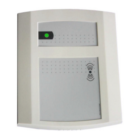
Abbildung 1: Lage der Anschlußkemmen und Bedienelemente Stecker Bezeichnung Funktion + / ∼ Spannungsversorgung - / ∼ R/A- RS485: RS232: T/B+ interner GND digitaler Eingang 1 digitaler Eingang 2 interner GND Relais Schließer Schirm Seite 8 von 28 FEIG ELECTRONIC GmbH... -
Page 9: Spannungsversorgung
Das Gerät ist mit einem elektronischen Halbleiterrelais ausgerüstet. Der Anschluß erfolgt an Stek- ker X2 Klemme [COM] und [NO]. Das Relais ist mit einer Miniatursicherung (siehe: Abbildung 1: Lage der Anschlußkemmen und Bedienelemente, „Fuse“) gegen Überlast geschützt. FEIG ELECTRONIC GmbH Seite 9 von 28... -
Page 10: Rs485 Schnittstelle (Id Rwa12.Abc-B /-Bk)
Leser mit RS232 Schnittstelle werden gem. Abbildung 4: Anschluß der RS232-Schnittstelle dem Leitrechner verbunden. Der Anschluß erfolgt über den Stecker X1 an den Klemmen [R/A-], [T/B+] und [GND]. Host T/B+ R/A- Reader Abbildung 4: Anschluß der RS232-Schnittstelle Seite 10 von 28 FEIG ELECTRONIC GmbH... -
Page 11: Inbetriebnahme
Beeper für 800 ms aktiv. Fehlerzustände werden über die rote LED und den Beeper signali- siert (siehe 5.2 LED und Beeper Anzeigen). ® 4. Anschließend kann eine weitere OBID MasterCard von dem multijob-Reader eingelesen werden. FEIG ELECTRONIC GmbH Seite 11 von 28... -
Page 12: Led Und Beeper Anzeigen
(CFG-EE) war fehlerhaft. Diese(r) wurde(n) mit Default-Wert(en) initialisiert. gelb blinken Offline-Mode Keine Kommunikation (multijob-Poll) zwischen Host und multijob-Reader gelb Online-Mode Kommunikation (multijob-Poll) zwischen Host und multijob-Reader besteht Werkseinstellung, kann individuell geändert werden. Werkseinstellung, kann individuell geändert werden. Seite 12 von 28 FEIG ELECTRONIC GmbH... -
Page 13: Geräteadresse (Online-Systeme)
DIP 3 DIP 4 Busbetrieb mit mehr als 16 Lesern: Die Adressvergabe erfolgt mit dem Leitrechner. HINWEIS: Da alle Geräte werksseitig die Adresse 0 eingestellt haben, müssen sie nacheinan- der angeklemmt und konfiguriert werden. FEIG ELECTRONIC GmbH Seite 13 von 28... -
Page 14: Anhang B: Technische Daten
• Datenübertragung mit Transponder 125 kHz / AM / halbduplex unterstützte Transponder ID CTx.A ID DTx.B ID DTx.C • • Kryptoprozessor ID RWA12.ABC-AK • ID RWA12.ABC-BK • Signalgeber • 1 x Bicolor-LED (rot, grün, orange) • 1 x Beeper • Halbleiter-Relais 1 x Schließer... -
Page 15: Anhang B1: Abmessungen
Montageanleitung ID RWA12.ABC-A / -B 6.1 Anhang B1: Abmessungen Abbildung 5: Montageabmessungen FEIG ELECTRONIC GmbH Seite 15 von 28... - Page 16 Composition of the information in this manual has been done to the best of our knowledge. FEIG ELECTRONIC GmbH does not guarantee the correctness and completeness of the details given in this manual and may not be held liable for damages ensuing from incorrect or incomplete information.
- Page 17 5. Initiation ........................24 ® 5.1 Configuration with OBID MasterCard................24 5.2 LED- and beeper Signals ....................25 5.3 Device address (Online-systems)..................26 6. ANNEX B: Technical data ..................27 6.1 ANNEX B1: Dimensions ....................28 FEIG ELECTRONIC GmbH Page 17 of 28...
-
Page 18: Safety Instructions - Please Read Carefully Prior To Initiation
• In case of a forced removal of the reader, the control line (as far as the relay is used) of the door/gate control may be shorted out and unauthorized opening becomes possible. Page 18 of 28 FEIG ELECTRONIC GmbH... -
Page 19: Delivery Contents
- 1 x 19 mm hole for wire 7 - 10 mm ∅ 1 x spare miniature fuse TR 5 (T1,6 A) 1 x Jumper (for J150, ID RW12.ABC-B / -BK) 1 x Installation- and operation manual FEIG ELECTRONIC GmbH Page 19 of 28... -
Page 20: Installation
5. Attach the transparent pane and fix the adhesive label: Only after having completed and checked all installation works, the transparent pane and the adhesive front label are being attached to the clean and non- greasy casing. Page 20 of 28 FEIG ELECTRONIC GmbH... -
Page 21: Reader Connection
Fig. 1: Position of the connecting terminals and the operational control connector term function + / ∼ power supply - / ∼ R/A- RS485: RS232: T/B+ internal GND digital input 1 digital input 2 internal GND relay make-contact shield FEIG ELECTRONIC GmbH Page 21 of 28... -
Page 22: Power Supply
The device is provided with an electronical semiconductor relay. The connecting is performed at connector X2, terminal [COM] and [NO]. The relay is protected against overcharge by means of a miniature fuse (see: Fig. 1: Position of the connecting terminals and the operational control, "Fuse"). Page 22 of 28 FEIG ELECTRONIC GmbH... -
Page 23: Rs485 Interface (Id Rwa12.Abc-B /-Bk)
Readers with RS232 interface are connected to the host according to Fig. 4: Connection of the RS232-interface. The connection is performed via the connector X1 at the terminals [R/A-], [T/B+] and [GND]. Host T/B+ R/A- Reader Fig. 4: Connection of the RS232-interface FEIG ELECTRONIC GmbH Page 23 of 28... -
Page 24: Initiation
800 ms. Error states are signalized by the red LED and the beeper (see 5.2 LED- and beeper Signals). ® 8. Then, the next OBID MasterCard can be read in by the multijob-Reader . Page 24 of 28 FEIG ELECTRONIC GmbH... -
Page 25: Led- And Beeper Signals
(have) been initialized with (a) default-value(s). yellow flashing Offline-Mode No communication (multijob-Poll) between host and multijob-Reader yellow Online-Mode communication (multijob-Poll) Host and multijob- Reader exists factory adjustment, may be changed individually. factory adjustment, may be changed individually. FEIG ELECTRONIC GmbH Page 25 of 28... -
Page 26: Device Address (Online-Systems)
Bus mode with more than 16 readers: The assignment of addresses is performed via the host. NOTE: As all devices are set with the address 0 (factory adjustment), they have to be connected and configured one after the other. Page 26 of 28 FEIG ELECTRONIC GmbH... -
Page 27: Annex B: Technical Data
• data transmission with transponder 125 kHz / AM / half duplex • supported transponders ID CTx.A ID DTx.B ID DTx.C • ID RWA12.ABC-AK • crypto processor • ID RWA12.ABC-BK • signal transmitter • 1 x bicolor-LED (red, green, orange) • 1 x beeper •... -
Page 28: Annex B1: Dimensions
® Identifikation System OBID 6.1 ANNEX B1: Dimensions Fig. 5: Installation dimensions Page 28 of 28 FEIG ELECTRONIC GmbH...
Need help?
Do you have a question about the ID RWA12.ABC-AK and is the answer not in the manual?
Questions and answers