Advertisement
Table of Contents
- 1 Table of Contents
- 2 General Information
- 3 Application
- 4 Description of Interfaces, Dip Switches and Displays
- 5 Mounting and Commissioning
- 6 Practical Safety Information
- 7 Preparing the Operating Pc or Service Notebook
- 8 The Configuration Tool
- 9 Optimising Data Transfer
- 10 Selecting a Password-Protected Serial Hub
- 11 Pin Assignment
- 12 Technical Data
- 13 Dimensions
- 14 Ordering Information
- Download this manual
Advertisement
Table of Contents

Subscribe to Our Youtube Channel
Related Manuals for Siemens 7XV5655-0BA00


Summary of Contents for Siemens 7XV5655-0BA00
- Page 1 7XV5655-0BA00 Manual C53000-G1176-C174-3 Application Instructions Serial Hub Ethernet hub for transmission of serial data or protocols from devices with an RS232/RS485/FO interface via Ethernet Copyright SIEMENS AG 2008...
-
Page 2: Table Of Contents
English 7XV5655-0BA00 CONTENTS GENERAL INFORMATION..........................3 APPLICATION................................8 DESCRIPTION OF INTERFACES, DIP SWITCHES AND DISPLAYS............11 MOUNTING AND COMMISSIONING ......................16 PRACTICAL SAFETY INFORMATION ......................19 PREPARING THE OPERATING PC OR SERVICE NOTEBOOK..............20 THE CONFIGURATION TOOL .........................27 OPTIMISING DATA TRANSFER ........................38 SELECTING A PASSWORD-PROTECTED SERIAL HUB................40 PIN ASSIGNMENT ...............................41... -
Page 3: General Information
Siemens office or from the addresses stated on the back of this manual. We should also like to point out that the contents of this product documentation are not part of any previous or existing agreement or legal relationship, nor are they apt to modify such an agreement or relationship. - Page 4 Directives in agreement with the generic standards EN 61000-6-2 and EN 61000-6-4 (for EMC Directive) and with the standard EN 60255-6 (for Low Voltage Directive) by Siemens AG. The device is designed and manufactured for application in industriel environment. The product conforms with the international standards of IEC 60255 and the German regulations of VDE 0435.
- Page 5 Warning The 7XV5655-0BA00 is specifically intended for installation in a switchgear cubicle or distribution box. After installation, the entire area around the terminals must be covered. Only then is the device sufficiently protected against impermissible contact with live parts.
- Page 6 English 7XV5655-0BA00 Warning! Hazardous voltages are present in this electrical equipment during operation. Severe personal injury or property damage can result if the device is not handled properly. Only qualified personnel should work on or around this equipment. The personnel must be thoroughly familiar with all warnings and maintenance procedures of this manual as well as the safety regulations.
- Page 7 English 7XV5655-0BA00 Scope of Supply • Serial Hub for DIN rail mounting • Gender changer, 9-way, male-male • CD with manual and configuration tool • Installation Instructions Unpacking and Repacking The devices are packed at the factory to meet the requirements of IEC 60255–21.
-
Page 8: Application
English 7XV5655-0BA00 Application General scope of application The Serial Hub is designed for operation in industrial zones and substations. The Serial Hub enables devices with serial interfaces (RS232, RS485, or FO) to convert data to the UDP protocol and to transmit and receive it via a TCP/IP network. This allows devices without dedicated network ports to exchange data via the Ethernet. - Page 9 7XV5655-0BA00 Application in Substations Using a 7XV5655-0BA00 Serial Hub with a fixed IP address, one or more SIPROTEC protection units can exchange serial data via an Ethernet network. On the operating PC, a configuration tool is used to link virtual COM port with the IP address of a Serial Hub.
- Page 10 English 7XV5655-0BA00 Features Protocol detection according to EN 60870-5-101/103 and DIGSI protocol (similar to IEC60870-5-103), UDP protocol with error detection and correction A 10-Mbit Ethernet interface (10BaseT) to the 10/100 Mbit network. RS232/RS485 (switchable port) or FO interface for data transfer.
-
Page 11: Description Of Interfaces, Dip Switches And Displays
RS232 Interface The terminal device (protection unit) (e.g. a SIPROTEC 4 unit) or a device from the ® SIEMENS accessory program (e.g. a 7XV5300 or 7XV5450 star coupler for operating two or more SIPROTEC devices) can be connected ® directly to the RS232 port. The data is exchanged between the protection unit and the Serial Hub via this interface. - Page 12 The data transfer rate is that of the RS232 interface. The terminal device (e.g. a SIPROTEC ® unit) or a further device from the Siemens accessory program (e.g. 7XV5300 or 7XV5450 star coupler for operating two or more SIPROTEC devices) can be ®...
- Page 13 English 7XV5655-0BA00 To use the FO interface, DIP switch S2-2 must be set to match the FO idle state of the communications partner (ON or OFF). DIP switch S2-1 for RS232/485 selection must be set to RS232. DIP switches S1-1 and S1-2 must be set to OFF (see Fig. 5).
- Page 14 English 7XV5655-0BA00 INIT button The INIT button is for resetting the Serial Hub to its factory (default) settings and should only be operated by technically qualified personnel. It can be used to set a defined baudrate locally for service work. The default baudrate is 9600 8N1.
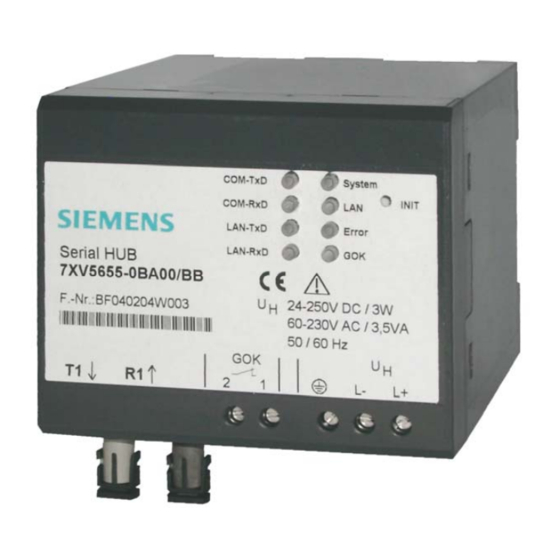
- Page 15 English 7XV5655-0BA00 Meaning of Displays The LEDs indicate the state of the device and have the following meaning: Fig. 6: Connectors, displays (LEDs) and INIT button • GOK Device run: switched on, operating voltage OK (GOK) device operational • System Slow flashing (approx.
-
Page 16: Mounting And Commissioning
English 7XV5655-0BA00 Mounting and Commissioning This chapter is intended for experienced commissioning staff. They must be familiar with the commissioning of protection and control systems, with the management of power systems and with the relevant safety rules and standards. Hardware modifications that might be needed in certain cases are explained. - Page 17 English 7XV5655-0BA00 Connecting the Device This describes connecting all data and power supply lines that are necessary for safe operation. In the case of electrical installation, follow the rules governing erection of power current equipment. Warning Always use wire end ferrules for stranded conductors.
- Page 18 English 7XV5655-0BA00 Connection to the Sub D connector The Sub D connector must be screwed tight after connection. The pin assignment is to be found in this manual (page 41 ff). Ethernet Connection The Serial Hub is connected to the network, i.e. a router or switch, using a patch cable via the RJ45 (10BaseT) connector.
-
Page 19: Practical Safety Information
English 7XV5655-0BA00 Practical Safety Information As is the case for all electrical equipment, there are some basic safety precautions to be taken. These safety precautions are primarily for your own safety but also prevent damage to the device. Settings not described in the manual and changes to the device electronics must only be carried out by an authorised vendor. -
Page 20: Preparing The Operating Pc Or Service Notebook
English 7XV5655-0BA00 Preparing the Operating PC or Service Notebook Before commissioning the Serial Hub, you must take the following precautions on the service PC (notebook). • Installation of the hub driver To operate the Serial Hub from a WINDOWS® application in which an Ethernet link will be established, a driver providing a virtual serial COM port must first be installed using the configuration tool. - Page 21 English 7XV5655-0BA00 Configuring the LAN Interface of the Operating PC There are two ways of configuring the Serial Hub on a PC/laptop using the configuration tool via its Ethernet interface: Direct PC <–> Serial Hub LAN connection with "cross-over patch cable"...
- Page 22 English 7XV5655-0BA00 The IP address is set under "Internet Protocol (TCP/IP)" by clicking the "Properties" button. A checkmark in "Show icon in notification area when connected … " has an icon display the status of the connection in the notification area.
- Page 23 English 7XV5655-0BA00 In the "Local area connection status" window, go to "Support" if you want to check the settings of the LAN interface. Close the window again with the "Close" button. After you have started the configuration tool, the connected Serial Hub is found automatically and can be configured (see Section "Configuration tool").
- Page 24 English 7XV5655-0BA00 PC <–> Serial Hub LAN connection in an existing network The Serial Hub is connected with a patch cable (not cross-over) to a hub or switch in an existing network to which the operating PC/laptop is also connected. The PC usually obtains a free IP address from the server.
- Page 25 English 7XV5655-0BA00 Using "HyperTerminal" via the Serial Interface of a PC This terminal program is supplied as a standard part of the operating system, e.g. WINDOWS® 2000 and WINDOWS® XP. Start HyperTerminal under: "Start Programs Accessories Communications HyperTerminal" Enter a name for the new connection, e.g.
- Page 26 English 7XV5655-0BA00 If the Serial Hub is connected to the PC, it is possible to listen in to the data traffic on the RS232 interface using HyperTerminal. This is useful, for example, when troubleshooting or to monitor the function of the Serial Hub after pressing the INIT button.
-
Page 27: The Configuration Tool
English 7XV5655-0BA00 The Configuration Tool Configuring the Serial Hub with the Configuration Tool The configuration tool provides a way of making "basic settings" such as Serial Hub name, IP address and baudrate of the Serial Hub. For this purpose, the configuration tool is started and finds all Serial Hubs in the same network segment which it then lists in a table. - Page 28 English 7XV5655-0BA00 Device Type Device Type Current firmware version Version Currently configured COM port (not available for Serial Hubs) Info If this entry is "true", the device is in connection mode and it is In Use not possible to make changes to parameterisation.
- Page 29 English 7XV5655-0BA00 Set IP Address Enter a fixed IP address, Subnet-Mask and Default-Gateway for operation of the Serial Hubs in a network. If the allocated IP-address and the Subnet-Mask are not compatible the properties can not be changed any more. In such an event please change the settings.
- Page 30 English 7XV5655-0BA00 Upload Firmware Look for the new firmware version and import with "Open" or by double-clicking. The firmware update resets the Serial Hub to its factory settings (default values). Passwords are not reset. If the message: "Can’t upload Firmware. See Logging"...
- Page 31 English 7XV5655-0BA00 View Event Log View current logfile (internal trace) Properties Type-specific configuration user interface For more information, see the relevant sections. Note regarding storage of the Properties “IP-Address“, “Name“ and “Password“ are saved in the Serial Hub. The virtual ”COM-Port“ and the associated ”IP-Address“ are saved in each operator PC.
- Page 32 English 7XV5655-0BA00 Properties Double-clicking the device entry in the overview window displays a dialog box in which further settings can be made. A detailed dialog box consisting of six setting tab cards opens: TCP/IP Settings "Info" displays the MAC address,...
- Page 33 English 7XV5655-0BA00 TC57 Settings (Ethernet) If a frame in TC57 format is received via the RS232 interface, it is sent immediately via the Ethernet without a "timeout". This procedure clearly increases the performance of the connection and ensures uninterrupted transmission of frames.
- Page 34 English 7XV5655-0BA00 RS232 Interface Settings (RS232 / RS485 / FO) These settings adapt the serial interface of the Serial Hub to that of the terminal device. The terminal device may, for example, be a protection unit with a serial interface (SIPROTEC ®...
- Page 35 English 7XV5655-0BA00 Port assignment This setting lists the virtual COM ports of the Serial Hubs. Delete Port Assignment can be used to delete the assigned virtual COM ports individually. The list provides a history of all devices ever configured and...
- Page 36 English 7XV5655-0BA00 INet Info This window provides up-to-date network information. Trace Route Ping The "Start" button transmits a ping to the Serial Hub to ascertain the throughput time of the telegrams in the network. Throughput time + 10ms = ideal "Total Timeout" here <10ms + 10ms = 20ms...
- Page 37 English 7XV5655-0BA00 About This window provides information about the program version and the date of creation of this configuration tool. If the PC has Internet access, you can double-click the image for direct access to our Download Area. All up-to-date documents, drivers and updates for our products are available there.
-
Page 38: Optimising Data Transfer
English 7XV5655-0BA00 Optimising Data Transfer Great emphasis has been placed on compatibility in the design of this device. Due to the Ethernet, there are, however, some minor restrictions. Data is not transmitted in bytes to the network, but Ethernet blocks are formed. This might result in minor delays. - Page 39 English 7XV5655-0BA00 Protocol Code TC57 for Transmission into the Ethernet This procedure considerably enhances transmission rates when TC57 compatible protocols are transmitted. If the RS232 interface detects a protocol packet of this type, it is transmitted as a block via the Ethernet immediately without waiting for a timeout to elapse.
-
Page 40: Selecting A Password-Protected Serial Hub
English 7XV5655-0BA00 Selecting a Password-Protected Serial Hub The password is for activation of the configuration mode with the configuration tool and for establishing the link. If no password is assigned, this must be entered in the configuration tool under 'Password required'=false. -
Page 41: Pin Assignment
English 7XV5655-0BA00 Pin Assignment The cables for RS232 and RS485 are connected to the same port and selected using the DIP switches. RS232 Interface SERIAL PORT Direction Definition 9-pin SubD connector Screen INPUT RXD Receive Data OUTPUT TXD Transmit Data... - Page 42 English 7XV5655-0BA00 Ethernet Interface Ethernet connector Name Definition RJ 45 Transmit Data+ Transmit Data- Receive Data+ not connected not connected Receive Data- not connected not connected Ethernet RJ45 connector Auxiliary Voltage and Earth Connection 3-way terminal block Name Definition Vaux...
- Page 43 English 7XV5655-0BA00 Connecting Cable RS232 connection options: 1) PC/laptop to the protection unit plug in serial DIGSI cable directly 2) Serial Hub to SIPROTEC 4 or plug in serial DIGSI cable via gender 7XV5300, 7XV5450, 7XV5550, 7XV5652 changer (male-male) to Serial Hub...
-
Page 44: Technical Data
English 7XV5655-0BA00 Technical Data 24 V – 250 V DC +/-20 % Auxiliary voltage 60 V – 230 V AC +/-20 % , 45-65 Hz, 2.5 W DC Power input 14 VA AC T 2A/250 V AC and 250 V DC Line-side fuse acc. - Page 45 English 7XV5655-0BA00 RS232 and RS485 Connection type 9-way SubD connector, 4/40 UNC screw connection Pin assignment See Pin Assignment Cable length RS232 Max. 10 m / 3280 feet Baud rate 2400 to 115200 baud, Rxd, Txd Parity : None, Even, Odd, Mark, Space...
- Page 46 3pos./neg. surges at 5s intervals interfaces, class III Warning The 7XV5655-0BA00 is specifically intended for installation in a switchgear cubicle or distribution box. After installation, the entire area around the terminals must be covered. Only then is the device sufficiently protected against impermissible contact with live parts.
- Page 47 English 7XV5655-0BA00 - Relay output common mode; 2 KV; 42 Ù; 0.5 µF differential mode : 1 KV; 42 Ω; 0.5 µF 10 V; 150 KHz – 80 MHz; 80 % AM, 1 KHz Conducted RF, amplitude-modulated IEC61000-4-6, Class III 0.5 mT;...
- Page 48 English 7XV5655-0BA00 Mechanical tests, vibration and shock stress - during transport Sinusoidal, 5 to 8 Hz : 7.5 mm ampl. Vibration IEC 60255-21-1, Class 2 8 to 150 Hz : 2 g accel., IEC 60068-2-6 20 cycles in 3 orthogonal axes Semi-sinusoidal, 15 g accel., 11 ms duration...
-
Page 49: Dimensions
English 7XV5655-0BA00 Dimensions 49 / 53 C53000-G1176-C174-3... -
Page 50: Ordering Information
English 7XV5655-0BA00 Ordering Information Name Order No. Serial Hub 7 X V 5 6 5 5 0 B A 0 0 10BaseT connection 10/100 Mbits, RJ45 connector Serial RS232/485 interface 9-way Sub D connector Gender changer (male-male) FO interface, ST connection DIN rail mounted device for 35mm rail Aux. - Page 51 Offenders will be liable for damages. All rights, including rights Änderungen vorbehalten created by patent grant or registration of a utility model or design, Subject to change without prior notice are reserved. Release 3.00.00 SIEMENS AKTIENGESELLSCHAFT...
- Page 52 Hinweise und Fragen zu diesem Produkt Defekte Geräte senden Sie bitte an richten Sie bitte an folgende Adresse: folgende Adresse: Siemens AG Siemens AG Power Transmission and Distribution Power Transmission and Distribution Energy Automation Energy Automation PTD Customer Support Center PTD EA P Rückwarenabteilung...
- Page 53 SIEMENS AKTIENGESELLSCHAFT...
Need help?
Do you have a question about the 7XV5655-0BA00 and is the answer not in the manual?
Questions and answers