
Related Manuals for Eaton Powerware 225 kVA Three-Phase Power Distribution Unit


Summary of Contents for Eaton Powerware 225 kVA Three-Phase Power Distribution Unit
- Page 1 Powerware Three−Phase Power Distribution Unit (PDU) ® 225 kVA Installation and Operation Manual Includes all 30–200kVA PDU Models and 225 kVA PDU Models with K1 and K13 Transformers...
- Page 2 Eaton, Powerware, X−Slot, LanSafe, and PowerXpert are registered trademarks and PowerTrust and ConnectPDU are trademarks of Eaton Corporation or its subsidiaries and affiliates. National Electrical Code and NEC are registered trademarks of National Fire Protection Association, Inc. Modbus is a registered trademark of Schneider Electric. HyperTerminal is a registered trademark of Hilgraeve.
-
Page 3: Table Of Contents
..........4−1 ® EATON Powerware 225 kVA PDU Installation and Operation Manual 164201629 Rev D www.powerware.com... - Page 4 ..................8−2 ® EATON Powerware 225 kVA PDU Installation and Operation Manual 164201629 Rev D www.powerware.com...
- Page 5 ..................A−57 ® EATON Powerware 225 kVA PDU Installation and Operation Manual 164201629 Rev D www.powerware.com...
- Page 6 3−5 Figure 4-1. Eaton REPO Switch ................
- Page 7 A−55 Figure A-42. Optional Eaton REPO Switch ..............
- Page 8 TABLE OF CONTENTS This page intentionally left blank. ® EATON Powerware 225 kVA PDU Installation and Operation Manual 164201629 Rev D www.powerware.com...
-
Page 9: Introduction
Engineer, or the warranty terms specified on page 10−1 become void. This service is offered as part of the sales contract for the UPS. Contact an Eaton service representative in advance (usually a two−week notice is required) to reserve a preferred startup date. -
Page 10: Figure 1-1. Powerware 225 Kva Three−Phase Pdu Cabinet
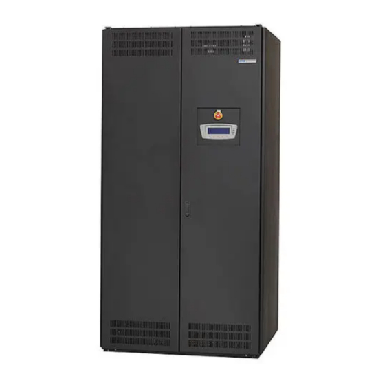
INTRODUCTION Figure 1-1. Powerware 225 kVA Three−Phase PDU Cabinet 1−2 ® EATON Powerware 225 kVA PDU Installation and Operation Manual 164201629 Rev D www.powerware.com... -
Page 11: Figure 1-2. Powerware 225 Kva Three−Phase Pdu Cabinet With Two Front−Mounted Sidecars
INTRODUCTION Figure 1-2. Powerware 225 kVA Three−Phase PDU Cabinet with Two Front−Mounted Sidecars ® 1−3 EATON Powerware 225 kVA PDU Installation and Operation Manual 164201629 Rev D www.powerware.com... -
Page 12: Figure 1-3. Powerware 225 Kva Three−Phase Pdu Cabinet With Two Side−Mounted Sidecars
INTRODUCTION Figure 1-3. Powerware 225 kVA Three−Phase PDU Cabinet with Two Side−Mounted Sidecars 1−4 ® EATON Powerware 225 kVA PDU Installation and Operation Manual 164201629 Rev D www.powerware.com... -
Page 13: Manual Restart
180°C. Transformer Shutdown Monitoring – A shutdown sensor is provided to shut down the PDU if the temperature of the transformer reaches 200°C. This feature can be enabled or disabled by an Eaton Customer Service Engineer. 1.1.6 Customer Interface The PDU has the following customer interface features. -
Page 14: Fault Monitoring
Fault Monitoring The following conditions can initiate a PDU shutdown and trip the PDU main input breaker CB1. These features can be enabled, disabled, or configured by an Eaton Customer Service Engineer. Overload Shutdown – An overload beyond a pre−set level is detected. This level can be set at 100%, 110%, or 125% of maximum rated output, or at a customer−specified level. -
Page 15: Transient Voltage Surge Suppression
The factory default configuration is set up for use with a normally−open switch. To use a normally−closed switch, the configuration must be changed during setup by an Eaton Customer Service Engineer. -
Page 16: Configurations
− one or two side−mounted sidecars with one or two 225A 42−circuit distribution panels Other configurations may be available. Please contact an Eaton sales representative. Using This Manual This manual describes how to install and operate the Powerware 225 kVA Three−Phase Power Distribution Unit. -
Page 17: Conventions Used In This Manual
This symbol indicates that you should not discard waste electrical or electronic equipment (WEEE) in the trash. For proper disposal, contact your local recycling/reuse or hazardous waste center. ® 1−9 EATON Powerware 225 kVA PDU Installation and Operation Manual 164201629 Rev D www.powerware.com... -
Page 18: Safety Warnings
Observe all DANGER, CAUTION, and WARNING notices affixed to the inside and outside of the equipment. 1−10 ® EATON Powerware 225 kVA PDU Installation and Operation Manual 164201629 Rev D www.powerware.com... -
Page 19: For More Information
Scheduling initial startup Regional locations and telephone numbers A question about any of the information in this manual A question this manual does not answer Please call the Eaton Corporation Help Desk for Powerware products at: 1−800−843−9433 1−919−870−3028 United States: 1−800−461−9166 ext 260... - Page 20 INTRODUCTION This page intentionally left blank. 1−12 ® EATON Powerware 225 kVA PDU Installation and Operation Manual 164201629 Rev D www.powerware.com...
-
Page 21: Section I - Installation
Section I Installation EATON Powerware ® 225 kVA PDU Installation and Operation Manual 164201629 Rev D www.powerware.com 1−1... - Page 22 1−2 EATON Powerware ® 225 kVA PDU Installation and Operation Manual 164201629 Rev D www.powerware.com...
-
Page 23: Pdu Installation Plan And Unpacking
Have authorized service personnel perform preliminary operational checks and startup. NOTE Startup and operational checks must be performed by an authorized Eaton Customer Service Engineer, or the warranty terms specified on page 10−1 become void. This service is offered as part of the sales contract for the PDU. -
Page 24: Environmental Considerations
Carefully inspect the outer packaging for evidence of damage during transit. C A U T I O N Do not install a damaged cabinet. Report any damage to the carrier and contact an Eaton service representative immediately. Use a forklift or pallet jack to move the packaged cabinet to the installation site, or as close as possible, before unpacking. -
Page 25: Figure 2-1. Powerware 225 Kva Three−Phase Pdu As Shipped On Pallet
Inspect the contents for any evidence of physical damage, and compare each item with the Bill of Lading. If damage has occurred or shortages are evident, contact an Eaton service representative immediately to determine the extent of the damage and its impact upon further installation. - Page 26 PDU INSTALLATION PLAN AND UNPACKING This page intentionally left blank. 2−4 ® EATON Powerware 225 kVA PDU Installation and Operation Manual 164201629 Rev D www.powerware.com...
-
Page 27: Installing The Pdu
The PDU is heavy (see Table A on page A−2). If unloading instructions are not closely followed, the cabinet may cause serious injury. Do not install a damaged cabinet. Report any damage to the carrier and contact an Eaton service representative immediately. -
Page 28: Figure 3-1. Removing Shipping Supports
10. After the 4 6 supports clear the floor, remove the hardware loosened in Step 8. Pull the 4 6 supports out from under the PDU cabinet. Discard or recycle them in a responsible manner. 3−2 ® EATON Powerware 225 kVA PDU Installation and Operation Manual 164201629 Rev D www.powerware.com... -
Page 29: Installing Pdu Power Wiring
If not already open, unfasten the front door latch and swing the doors open. Loosen the screws securing the inside distribution panel doors and swing the doors open. ® 3−3 EATON Powerware 225 kVA PDU Installation and Operation Manual 164201629 Rev D www.powerware.com... - Page 30 (CT) opposite the breaker terminal to the breaker lug (see Figure 3-2). Use care when bending and routing the wires through the CTs. 3−4 ® EATON Powerware 225 kVA PDU Installation and Operation Manual 164201629 Rev D www.powerware.com...
-
Page 31: Figure 3-2. Bcm Ct Wiring
If the optional EMS Level 3 BCM is installed, route branch wiring through the CT opposite the breaker terminal to the breaker lug (see Figure 3-2). Use care when bending and routing the wires through the CTs. ® 3−5 EATON Powerware 225 kVA PDU Installation and Operation Manual 164201629 Rev D www.powerware.com... -
Page 32: Installing Tb1 And Tb2 Interface Connections
Route and connect the wiring. Close the inside distribution panel doors and secure with screws. Close the outside doors and secure the latch. 3−6 ® EATON Powerware 225 kVA PDU Installation and Operation Manual 164201629 Rev D www.powerware.com... -
Page 33: Initial Startup
- Adequate workspace exists around the PDU and other cabinets. - Adequate lighting is provided around the PDU. - A 120V service outlet is located within 7.5 meters (25 feet) of the PDU. - Startup and operational checks are performed by an authorized Eaton Customer Service Engineer. ® 3−7... - Page 34 INSTALLING THE PDU Notes _________________________________________________________________________ _________________________________________________________________________ _________________________________________________________________________ _________________________________________________________________________ _________________________________________________________________________ _________________________________________________________________________ _________________________________________________________________________ _________________________________________________________________________ _________________________________________________________________________ _________________________________________________________________________ _________________________________________________________________________ _________________________________________________________________________ _________________________________________________________________________ _________________________________________________________________________ _________________________________________________________________________ _________________________________________________________________________ 3−8 ® EATON Powerware 225 kVA PDU Installation and Operation Manual 164201629 Rev D www.powerware.com...
-
Page 35: Installing A Remote Emergency Power−Off Switch
Eaton Customer Service Engineer NOTE This procedure is intended to be used for the installation of the Eaton REPO switch. If installing another manufacturer’s switch, use this procedure only as a guide. -
Page 36: Figure 4-2. Repo Switch Wiring
NOTE The REPO switch must be a normally−open or normally−closed latching-type switch not tied into any other circuits. The factory default configuration is set up for use with a normally−open switch. To use a normally−closed switch, the configuration must be changed during setup by an Eaton Customer Service Engineer NOTE The REPO switch wiring must be in accordance with NEC Article 725 Class 2 requirements. - Page 37 11. When all wiring is complete, close the inside distribution panel doors and secure with screws. 12. Close the outside doors and secure the latch. ® 4−3 EATON Powerware 225 kVA PDU Installation and Operation Manual 164201629 Rev D www.powerware.com...
- Page 38 INSTALLING A REMOTE EMERGENCY POWER−OFF SWITCH This page intentionally left blank. 4−4 ® EATON Powerware 225 kVA PDU Installation and Operation Manual 164201629 Rev D www.powerware.com...
- Page 39 Section II Operation EATON Powerware ® 225 kVA PDU Installation and Operation Manual 164201629 Rev D www.powerware.com 4−5...
- Page 40 4−6 EATON Powerware ® 225 kVA PDU Installation and Operation Manual 164201629 Rev D www.powerware.com...
-
Page 41: Understanding Pdu Operation
Figure 5-3 shows the path of electrical power through the PDU with a distribution panelboard and subfeed breakers. ® 5−1 EATON Powerware 225 kVA PDU Installation and Operation Manual 164201629 Rev D www.powerware.com... -
Page 42: Figure 5-1. Current Path Through The Pdu With Distribution Panelboards
Circuit Breaker Circuit Breaker 42-Pole Panelboard 42-Pole Panelboard (Optional) POWER DISTRIBUTION UNIT Main Power Flow Figure 5-1. Current Path Through the PDU with Distribution Panelboards 5−2 ® EATON Powerware 225 kVA PDU Installation and Operation Manual 164201629 Rev D www.powerware.com... -
Page 43: Figure 5-2. Current Path Through The Pdu With Subfeed Breakers
Breaker 3 Output Subfeed Output Subfeed Breaker 8 Breaker 4 POWER DISTRIBUTION UNIT Main Power Flow Figure 5-2. Current Path Through the PDU with Subfeed Breakers ® 5−3 EATON Powerware 225 kVA PDU Installation and Operation Manual 164201629 Rev D www.powerware.com... -
Page 44: Figure 5-3. Current Path Through The Pdu With Distribution Panelboard And Subfeed Breakers
42-Pole Panelboard Output Subfeed Breaker 4 POWER DISTRIBUTION UNIT Main Power Flow Figure 5-3. Current Path Through the PDU with Distribution Panelboard and Subfeed Breakers 5−4 ® EATON Powerware 225 kVA PDU Installation and Operation Manual 164201629 Rev D www.powerware.com... -
Page 45: Pdu Operating Instructions
NOTE Before starting the PDU, ensure all installation tasks are complete and a preliminary startup has been performed by an Eaton Customer Service Engineer. The preliminary startup verifies all electrical interconnections to ensure the installation was successful and the PDU operates properly. -
Page 46: Figure 6-1. Pdu Controls - Doors Closed
PDU OPERATING INSTRUCTIONS Control Panel Figure 6-1. PDU Controls – Doors Closed 6−2 ® EATON Powerware 225 kVA PDU Installation and Operation Manual 164201629 Rev D www.powerware.com... -
Page 47: Figure 6-2. Pdu Controls - Doors Removed With Distribution Panels
NOTE The PDU is shown with both left and right distribution panels. However, the installed configuration may contain only a left or right distribution panel. Figure 6-2. PDU Controls – Doors Removed with Distribution Panels ® 6−3 EATON Powerware 225 kVA PDU Installation and Operation Manual 164201629 Rev D www.powerware.com... -
Page 48: Figure 6-3. Pdu Controls - Doors Removed With A Distribution Panel And Subfeed Breakers
Figure 6-3. PDU Controls – Doors Removed with a Distribution Panel and Subfeed Breakers 6−4 ® EATON Powerware 225 kVA PDU Installation and Operation Manual 164201629 Rev D www.powerware.com... -
Page 49: Figure 6-4. Pdu Controls - Doors Removed With Subfeed Breakers
NOTE The PDU is shown with eight subfeed breakers. However, the installed configuration may contain one to eight subfeed breakers. Figure 6-4. PDU Controls – Doors Removed with Subfeed Breakers ® 6−5 EATON Powerware 225 kVA PDU Installation and Operation Manual 164201629 Rev D www.powerware.com... -
Page 50: Figure 6-5. Front−Mounted Sidecar Controls - Doors Removed With Distribution Panels
NOTE The sidecar is shown with both top and bottom distribution panels. However, the installed configuration may contain only a top or bottom distribution panel. Figure 6-5. Front−Mounted Sidecar Controls – Doors Removed with Distribution Panels 6−6 ® EATON Powerware 225 kVA PDU Installation and Operation Manual 164201629 Rev D www.powerware.com... -
Page 51: Figure 6-6. Side−Mounted Sidecar Controls - Doors Removed With Distribution Panels
NOTE The sidecar is shown with both top and bottom distribution panels. However, the installed configuration may contain only a top or bottom distribution panel. Figure 6-6. Side−Mounted Sidecar Controls – Doors Removed with Distribution Panels ® 6−7 EATON Powerware 225 kVA PDU Installation and Operation Manual 164201629 Rev D www.powerware.com... -
Page 52: Using The Control Panel
PDU. See paragraph 6.4, PDU Operating Instructions," for specific procedures. When the unit powers up, the screen displays the Eaton | Powerware logo as shown in Figure 6-7. To advance to the main menu and mimic screen, press any control panel pushbutton once. -
Page 53: System Events
LCD in the PDU status area. This message is also written to the Active Events Log and may be added to the History Log. The messages are divided into four categories: alarms, notices, status, and commands. ® 6−9 EATON Powerware 225 kVA PDU Installation and Operation Manual 164201629 Rev D www.powerware.com... -
Page 54: Using The Lcd And Pushbuttons
SETUP CONTROL Figure 6-8. Parts of the LCD The PDU status area alternately displays Eaton EMS−PDU name, the current date and time, and any current alarm messages. The information area contains data about PDU status and operations. The menu bar lists the available screens. To select a screen, press the pushbutton under the screen. -
Page 55: Display And Metering Screens
Setup screens. Returns to the main System Setup Level screen from a setup submenu. Up or down arrows scroll through screens and lists or highlight settings. Left or right arrows select or adjust settings displayed on the screen. ® 6−11 EATON Powerware 225 kVA PDU Installation and Operation Manual 164201629 Rev D www.powerware.com... -
Page 56: Mimic Screen
Events, Meters, Profile, or Setup screens, press the pushbutton on the current menu bar. The mimic screen shows the internal components of the PDU and a real-time graphical representation of the operating status of the system. EATON EMS-PDU 000.0 000.0 000.0 000.0 000.0... - Page 57 Press the SETUP pushbutton on the main menu bar to display the System Setup Level 0 Screen. Use the up or down arrow pushbuttons to highlight the setup function screen desired, then press the SELECT pushbutton to display the function screen. ® 6−13 EATON Powerware 225 kVA PDU Installation and Operation Manual 164201629 Rev D www.powerware.com...
- Page 58 SELECT pushbutton To return to the System Setup screen, press the return arrow pushbutton 6−14 ® EATON Powerware 225 kVA PDU Installation and Operation Manual 164201629 Rev D www.powerware.com...
- Page 59 Press SAVE, RETRY, or ABORT. If SAVE or ABORT is pressed, the action is completed, and the System Setup screen displays. If RETRY is pressed, the Unit Name screen is redisplayed. ® 6−15 EATON Powerware 225 kVA PDU Installation and Operation Manual 164201629 Rev D www.powerware.com...
-
Page 60: Tvss Status Indicators
Verify that the OFF and ALARM status indicators on the PDU control panel are illuminated and the horn is sounding. Press any key to silence the horn. Set the date and time. 6−16 ® EATON Powerware 225 kVA PDU Installation and Operation Manual 164201629 Rev D www.powerware.com... -
Page 61: Restarting The Pdu
If manual restart is enabled, the main input breaker will trip when input power to the PDU is lost. To restart the PDU: NOTE Manual restart must be enabled by an Eaton Customer Service Engineer. Unfasten the front door latch and swing the doors open. -
Page 62: Using The Emergency Power−Off Switch
All power to the critical load is lost when the REPO switch is activated in the following step. Use this feature only when you want to de-energize the critical load. NOTE The following instructions are for the Eaton−supplied REPO switch. A customer−supplied REPO switch may not activate in the same manner; refer to the operating instructions provided with the switch. -
Page 63: Shutdown
(CB1) directly or use the control panel. To remove power from the PDU completely, turn off utility power to the PDU. Close the outside doors and secure the latch. ® 6−19 EATON Powerware 225 kVA PDU Installation and Operation Manual 164201629 Rev D www.powerware.com... - Page 64 PDU OPERATING INSTRUCTIONS This page intentionally left blank. 6−20 ® EATON Powerware 225 kVA PDU Installation and Operation Manual 164201629 Rev D www.powerware.com...
-
Page 65: Communication
For installation and setup of the Powerware ConnectPDU Web/SNMP Card, see paragraph 7.4. For installation and setup of all other X−Slot cards, please contact an Eaton service representative (see page 1−11). Refer to the manual supplied with the X−Slot card for user instructions. -
Page 66: Terminal Mode
1, 2, 3, 4, and 5 are substituted for the five pushbuttons on the PDU LCD screen. The various screens are invoked using the same procedure described in Chapter 6, PDU Operating Instructions. 7−2 ® EATON Powerware 225 kVA PDU Installation and Operation Manual 164201629 Rev D www.powerware.com... -
Page 67: Profile Log
Carriage Return Character (ASCII 13) <CR> Line Feed (ASCII 10) <LF> An alarm that clears is prefixed by the word CLEAR" in the history log. ® 7−3 EATON Powerware 225 kVA PDU Installation and Operation Manual 164201629 Rev D www.powerware.com... -
Page 68: Figure 7-2. Sample History Log
04/18/2006 07:36:01.225 ALARM: Input Phase Loss 2 04/18/2006 07:36:01.225 ALARM: Input Phase Loss 3 04/18/2006 08:05:32.565 STATUS: Control Power Status On Figure 7-2. Sample History Log 7−4 ® EATON Powerware 225 kVA PDU Installation and Operation Manual 164201629 Rev D www.powerware.com... -
Page 69: Connectpdu Web/Snmp Card
- DNS (name server) IP Address _____ . _____ . _____ . _____ - Host Name ________________________ Refer to the Powerware ConnectPDU Web/SNMP Card User’s Guide PDF downloaded from powerware.com. ® 7−5 EATON Powerware 225 kVA PDU Installation and Operation Manual 164201629 Rev D www.powerware.com... -
Page 70: Install The Card
To configure the card remotely through a network using a Web browser or Telnet (or similar) utility, refer to the Powerware ConnectPDU Web/SNMP Card User’s Guide PDF downloaded from powerware.com. 7−6 ® EATON Powerware 225 kVA PDU Installation and Operation Manual 164201629 Rev D www.powerware.com... -
Page 71: Connect The Card
Verify that the card has power (one or more LEDs on the card are illuminated). The PDU logic power should be turned on. Type your password (the default is admin) and press Enter. The Main Menu screen appears. ® 7−7 EATON Powerware 225 kVA PDU Installation and Operation Manual 164201629 Rev D www.powerware.com... -
Page 72: Configure The Card
NOTE Once the card is reachable on the network, you can use a Web browser, Telnet, or similar utility to adjust any of the configuration settings. The menus are identical to those seen during serial configuration and are password−protected for Superuser access only. 7−8 ® EATON Powerware 225 kVA PDU Installation and Operation Manual 164201629 Rev D www.powerware.com... -
Page 73: Modbus Register Mapping
Greater than 150% overload on phase A BOOL Status Greater than 150% overload on phase B BOOL Status Greater than 150% overload on phase C BOOL Status ® 7−9 EATON Powerware 225 kVA PDU Installation and Operation Manual 164201629 Rev D www.powerware.com... -
Page 74: Read Input Registers
INPUT FREQUENCY INPUT VOLTS PHASE A 2828 Volts INPUT VOLTS PHASE B 2835 Volts INPUT VOLTS PHASE C 2840 Volts LOAD CURRENT PHASE A Amps 7−10 ® EATON Powerware 225 kVA PDU Installation and Operation Manual 164201629 Rev D www.powerware.com... - Page 75 LOAD CURRENT PHASE C BAR CHART 2266 Amps OUTPUT VOLTS A 1230 Volts OUTPUT VOLTS B 1223 Volts OUTPUT VOLTS C 1227 Volts NEUTRAL CURRENT Amps ® 7−11 EATON Powerware 225 kVA PDU Installation and Operation Manual 164201629 Rev D www.powerware.com...
- Page 76 COMMUNICATION This page intentionally left blank. 7−12 ® EATON Powerware 225 kVA PDU Installation and Operation Manual 164201629 Rev D www.powerware.com...
-
Page 77: Pdu Maintenance
8.2.3 ANNUAL Maintenance Annual preventive maintenance, if required, should be performed only by authorized service personnel familiar with maintenance and servicing of the PDU. Contact an Eaton service representative for more information about service offerings. ® 8−1 EATON Powerware 225 kVA PDU Installation and Operation Manual... -
Page 78: Short Circuits
Tripping of protective devices due to low impedance short circuits should be thoroughly investigated for damage to conductors, insulation, and the protective devices in accordance with the manufacturer’s recommendations. 8−2 ® EATON Powerware 225 kVA PDU Installation and Operation Manual 164201629 Rev D www.powerware.com... -
Page 79: Product Specifications
Electrostatic Discharge (ESD) Meets IEC 801-2 specifications. Withstands up to 25 kV pulse without Immunity damage and with no disturbance or adverse effect to the critical load. ® 9−1 EATON Powerware 225 kVA PDU Installation and Operation Manual 164201629 Rev D www.powerware.com... - Page 80 PRODUCT SPECIFICATIONS This page intentionally left blank. 9−2 ® EATON Powerware 225 kVA PDU Installation and Operation Manual 164201629 Rev D www.powerware.com...
-
Page 81: Warranty
Any Warranted Items repaired or replaced pursuant to this Warranty will be warranted for the remaining portion of the original Warranty subject to all the terms thereof. Eaton does not provide a labor warranty for Product located outside of the fifty (50) United States or the District of Columbia. - Page 82 WARRANTY This page intentionally left blank. 10−2 ® EATON Powerware 225 kVA PDU Installation and Operation Manual 164201629 Rev D www.powerware.com...
-
Page 83: Installation Reference
The PDU equipment operating environment for the installed PDU configuration must meet the weight requirements shown in Table A and size requirements shown in Figure A-4 through Figure A-17. ® A−1 EATON Powerware 225 kVA PDU Installation and Operation Manual 164201629 Rev D www.powerware.com... - Page 84 125 kg (275 lb) to installed weight. For each additional side−mounted sidecar, add 118 kg (260 lb) shipping weight and 114 kg (250 lb) to installed weight. A−2 ® EATON Powerware 225 kVA PDU Installation and Operation Manual 164201629 Rev D www.powerware.com...
- Page 85 Ambient Temperature Range: 0–40°C (32–104°F) Recommended Operating Range: 20–25°C (68–77°F) Maximum Relative Humidity: 95%, noncondensing The PDU cooling requirements are shown in Table C through Table E. ® A−3 EATON Powerware 225 kVA PDU Installation and Operation Manual 164201629 Rev D www.powerware.com...
- Page 86 15973 208/120 7920 27031 208/120 6120 20887 208/120 5760 19659 208/120 8700 29693 208/120 7140 24369 208/120 6660 22730 208/120 9900 33788 208/120 8040 27440 A−4 ® EATON Powerware 225 kVA PDU Installation and Operation Manual 164201629 Rev D www.powerware.com...
- Page 87 14376 208/120 7128 24328 208/120 5508 18799 208/120 5184 17693 208/120 7830 26724 208/120 6426 21932 208/120 5994 20457 208/120 8910 30409 208/120 7236 24696 ® A−5 EATON Powerware 225 kVA PDU Installation and Operation Manual 164201629 Rev D www.powerware.com...
-
Page 88: Figure A-1. Powerware 225 Kva Pdu
INSTALLATION REFERENCE Figure A-1. Powerware 225 kVA PDU A−6 ® EATON Powerware 225 kVA PDU Installation and Operation Manual 164201629 Rev D www.powerware.com... -
Page 89: Figure A-2. Powerware 225 Kva Pdu With Front−Mounted Sidecars
INSTALLATION REFERENCE Front−Mounted Sidecar Front−Mounted Sidecar (Optional) (Optional) Figure A-2. Powerware 225 kVA PDU with Front−Mounted Sidecars ® A−7 EATON Powerware 225 kVA PDU Installation and Operation Manual 164201629 Rev D www.powerware.com... -
Page 90: Figure A-3. Powerware 225 Kva Pdu With Side−Mounted Sidecars
INSTALLATION REFERENCE Side−Mounted Sidecar Side−Mounted Sidecar (Optional) (Optional) Figure A-3. Powerware 225 kVA PDU with Side−Mounted Sidecars A−8 ® EATON Powerware 225 kVA PDU Installation and Operation Manual 164201629 Rev D www.powerware.com... -
Page 91: Figure A-4. Pdu Dimensions - Front And Right Side View
INSTALLATION REFERENCE Front View Right Side View Dimensions are in millimeters [inches]. Figure A-4. PDU Dimensions – Front and Right Side View ® A−9 EATON Powerware 225 kVA PDU Installation and Operation Manual 164201629 Rev D www.powerware.com... -
Page 92: Figure A-5. Pdu Dimensions - Top And Bottom View
INSTALLATION REFERENCE Top View Bottom View Dimensions are in millimeters [inches]. Figure A-5. PDU Dimensions – Top and Bottom View A−10 ® EATON Powerware 225 kVA PDU Installation and Operation Manual 164201629 Rev D www.powerware.com... -
Page 93: Figure A-6. Pdu Dimensions - Front View With Front−Mounted Left Sidecar
INSTALLATION REFERENCE Front View Dimensions are in millimeters [inches]. Figure A-6. PDU Dimensions – Front View with Front−Mounted Left Sidecar ® A−11 EATON Powerware 225 kVA PDU Installation and Operation Manual 164201629 Rev D www.powerware.com... -
Page 94: Figure A-7. Pdu Dimensions - Top And Bottom View With Front−Mounted Left Sidecar
INSTALLATION REFERENCE Top View Bottom View Dimensions are in millimeters [inches]. Figure A-7. PDU Dimensions – Top and Bottom View with Front−Mounted Left Sidecar A−12 ® EATON Powerware 225 kVA PDU Installation and Operation Manual 164201629 Rev D www.powerware.com... -
Page 95: Figure A-8. Pdu Dimensions - Front View With Front−Mounted Right Sidecar
INSTALLATION REFERENCE Front View Dimensions are in millimeters [inches]. Figure A-8. PDU Dimensions – Front View with Front−Mounted Right Sidecar ® A−13 EATON Powerware 225 kVA PDU Installation and Operation Manual 164201629 Rev D www.powerware.com... -
Page 96: Figure A-9. Pdu Dimensions - Top And Bottom View With Front−Mounted Right Sidecar
INSTALLATION REFERENCE Top View Bottom View Dimensions are in millimeters [inches]. Figure A-9. PDU Dimensions – Top and Bottom View with Front−Mounted Right Sidecar A−14 ® EATON Powerware 225 kVA PDU Installation and Operation Manual 164201629 Rev D www.powerware.com... -
Page 97: Figure A-10. Pdu Dimensions - Front View With Front−Mounted Left And Right Sidecars
INSTALLATION REFERENCE Front View Dimensions are in millimeters [inches]. Figure A-10. PDU Dimensions – Front View with Front−Mounted Left and Right Sidecars ® A−15 EATON Powerware 225 kVA PDU Installation and Operation Manual 164201629 Rev D www.powerware.com... -
Page 98: Figure A-11. Pdu Dimensions - Top And Bottom View With Front−Mounted Left And Right Sidecar
INSTALLATION REFERENCE Top View Bottom View Dimensions are in millimeters [inches]. Figure A-11. PDU Dimensions – Top and Bottom View with Front−Mounted Left and Right Sidecar A−16 ® EATON Powerware 225 kVA PDU Installation and Operation Manual 164201629 Rev D www.powerware.com... -
Page 99: Figure A-12. Pdu Dimensions - Front View With Side−Mounted Left Sidecar
INSTALLATION REFERENCE Front View Dimensions are in millimeters [inches]. Figure A-12. PDU Dimensions – Front View with Side−Mounted Left Sidecar ® A−17 EATON Powerware 225 kVA PDU Installation and Operation Manual 164201629 Rev D www.powerware.com... -
Page 100: Figure A-13. Pdu Dimensions - Top And Bottom View With Side−Mounted Left Sidecar
INSTALLATION REFERENCE Top View Bottom View Dimensions are in millimeters [inches]. Figure A-13. PDU Dimensions – Top and Bottom View with Side−Mounted Left Sidecar A−18 ® EATON Powerware 225 kVA PDU Installation and Operation Manual 164201629 Rev D www.powerware.com... -
Page 101: Figure A-14. Pdu Dimensions - Front View With Side−Mounted Right Sidecar
INSTALLATION REFERENCE Front View Dimensions are in millimeters [inches]. Figure A-14. PDU Dimensions – Front View with Side−Mounted Right Sidecar ® A−19 EATON Powerware 225 kVA PDU Installation and Operation Manual 164201629 Rev D www.powerware.com... -
Page 102: Figure A-15. Pdu Dimensions - Top And Bottom View With Side−Mounted Right Sidecar
INSTALLATION REFERENCE Top View Bottom View Dimensions are in millimeters [inches]. Figure A-15. PDU Dimensions – Top and Bottom View with Side−Mounted Right Sidecar A−20 ® EATON Powerware 225 kVA PDU Installation and Operation Manual 164201629 Rev D www.powerware.com... -
Page 103: Figure A-16. Pdu Dimensions - Front View With Side−Mounted Left And Right Sidecars
INSTALLATION REFERENCE Front View Dimensions are in millimeters [inches]. Figure A-16. PDU Dimensions – Front View with Side−Mounted Left and Right Sidecars ® A−21 EATON Powerware 225 kVA PDU Installation and Operation Manual 164201629 Rev D www.powerware.com... -
Page 104: Figure A-17. Pdu Dimensions - Top And Bottom View With Side−Mounted Left And Right Sidecar
INSTALLATION REFERENCE Top View Bottom View Dimensions are in millimeters [inches]. Figure A-17. PDU Dimensions – Top and Bottom View with Side−Mounted Left and Right Sidecar A−22 ® EATON Powerware 225 kVA PDU Installation and Operation Manual 164201629 Rev D www.powerware.com... -
Page 105: Oneline Drawings And Schematic
Figure A-23 on 30–225kVA 208/120 optional sidecars with page A−29 distribution panel output Figure A-24 on 30–225kVA 208/120 Distribution panel schematic page A−30 ® A−23 EATON Powerware 225 kVA PDU Installation and Operation Manual 164201629 Rev D www.powerware.com... -
Page 106: Figure A-18. Pdu Distribution Panel Output - 208V Input And 208V Output
Sidecars are available with options for one or two 42-pole 225A distribution panels. Figure A-18. PDU Distribution Panel Output – 208V Input and 208V Output A−24 ® EATON Powerware 225 kVA PDU Installation and Operation Manual 164201629 Rev D www.powerware.com... -
Page 107: Figure A-19. Pdu Distribution Panel And Subfeed Breaker Output - 208V Input And 208V Output
Sidecars are available with options for one or two 42-pole 225A distribution panels. Figure A-19. PDU Distribution Panel and Subfeed Breaker Output – 208V Input and 208V Output ® A−25 EATON Powerware 225 kVA PDU Installation and Operation Manual 164201629 Rev D www.powerware.com... -
Page 108: Figure A-20. Pdu Subfeed Breaker Output - 208V Input And 208V Output
Sidecars are available with options for one or two 42-pole 225A distribution panels. Figure A-20. PDU Subfeed Breaker Output – 208V Input and 208V Output A−26 ® EATON Powerware 225 kVA PDU Installation and Operation Manual 164201629 Rev D www.powerware.com... -
Page 109: Figure A-21. Pdu Distribution Panel Output - 480V And 600V Input, And 208/120V Output
Sidecars are available with options for one or two 42-pole 225A distribution panels. Figure A-21. PDU Distribution Panel Output – 480V and 600V Input, and 208/120V Output ® A−27 EATON Powerware 225 kVA PDU Installation and Operation Manual 164201629 Rev D www.powerware.com... -
Page 110: Figure A-22. Pdu Distribution Panel And Subfeed Breaker Output - 480V And 600V Input, And 208/120V Output
Sidecars are available with options for one or two 42-pole 225A distribution panels. Figure A-22. PDU Distribution Panel and Subfeed Breaker Output – 480V and 600V Input, and 208/120V Output A−28 ® EATON Powerware 225 kVA PDU Installation and Operation Manual 164201629 Rev D www.powerware.com... -
Page 111: Figure A-23. Pdu Subfeed Breaker Output - 480V And 600V Input, And 208/120V Output
Sidecars are available with options for one or two 42-pole 225A distribution panels. Figure A-23. PDU Subfeed Breaker Output – 480V and 600V Input, and 208/120V Output ® A−29 EATON Powerware 225 kVA PDU Installation and Operation Manual 164201629 Rev D www.powerware.com... -
Page 112: Figure A-24. Pdu Distribution Panel Schematic
INSTALLATION REFERENCE Figure A-24. PDU Distribution Panel Schematic A−30 ® EATON Powerware 225 kVA PDU Installation and Operation Manual 164201629 Rev D www.powerware.com... -
Page 113: Power Wiring Installation Notes
All PDU products can accommodate a double-sized neutral. ® A−31 EATON Powerware 225 kVA PDU Installation and Operation Manual 164201629 Rev D www.powerware.com... - Page 114 NOTE Callout letters map to Figure A-21 on page A−27, Figure A-22 on page A−28, and Figure A-23 on page A−29. A−32 ® EATON Powerware 225 kVA PDU Installation and Operation Manual 164201629 Rev D www.powerware.com...
- Page 115 Maximum output ratings are to be in accordance with the rating label on the PDU. The total combined load is not to exceed the maximum output rating. NOTE Callout letters map to Figure A-21 through Figure A-23. ® A−33 EATON Powerware 225 kVA PDU Installation and Operation Manual 164201629 Rev D www.powerware.com...
- Page 116 Input Voltage kVA Rating Size Standard High 125A 175A 300A 350A 450A 600A 125A 150A 200A 225A 300A 350A 100A 125A 150A 200A 250A 300A A−34 ® EATON Powerware 225 kVA PDU Installation and Operation Manual 164201629 Rev D www.powerware.com...
- Page 117 2 – 300 kcmil 5/16" Hex 31 (275) Neutral 4 – 3/0 31 (275) 5/16" Hex Customer Ground Ground 1 – 1/0 31 (275) 5/16" Hex ® A−35 EATON Powerware 225 kVA PDU Installation and Operation Manual 164201629 Rev D www.powerware.com...
- Page 118 5/16" Hex 350A Phase C 2 – 2/0 31 (275) 5/16" Hex Neutral Not required Customer Ground Ground 1 – 1/0 31 (275) 5/16" Hex A−36 ® EATON Powerware 225 kVA PDU Installation and Operation Manual 164201629 Rev D www.powerware.com...
- Page 119 5/16" Hex 300A Phase C 2 – 1/0 31 (275) 5/16" Hex Neutral Not required Customer Ground Ground 1 – 1/0 31 (275) 5/16" Hex ® A−37 EATON Powerware 225 kVA PDU Installation and Operation Manual 164201629 Rev D www.powerware.com...
- Page 120 #10–#14: 2.3 (20) Panel Breakers to Critical Load #4–#6: 4.0 (35) Ground 84 – #4−#14 or 2 x #12−#14 2.8 (25) Slotted #10–#14: 2.3 (20) A−38 ® EATON Powerware 225 kVA PDU Installation and Operation Manual 164201629 Rev D www.powerware.com...
-
Page 121: Location Of Pdu Conduit Landing And Wire Entry Plates
NOTE Sidecars are optional. Figure A-25. PDU Conduit Landing Plate Locations – Top View of PDU with Front−Mounted Sidecars ® A−39 EATON Powerware 225 kVA PDU Installation and Operation Manual 164201629 Rev D www.powerware.com... -
Page 122: Figure A-26. Pdu Conduit Landing Plate Locations - Bottom View Of Pdu With Front−Mounted Sidecars
NOTE Sidecars are optional. Figure A-26. PDU Conduit Landing Plate Locations – Bottom View of PDU with Front−Mounted Sidecars A−40 ® EATON Powerware 225 kVA PDU Installation and Operation Manual 164201629 Rev D www.powerware.com... -
Page 123: Figure A-27. Pdu Conduit Landing Plate Locations - Top View Of Pdu With Side−Mounted Sidecars
NOTE Sidecars are optional. Figure A-27. PDU Conduit Landing Plate Locations – Top View of PDU with Side−Mounted Sidecars ® A−41 EATON Powerware 225 kVA PDU Installation and Operation Manual 164201629 Rev D www.powerware.com... -
Page 124: Figure A-28. Pdu Conduit Landing Plate Locations - Bottom View Of Pdu With Side−Mounted Sidecars
NOTE Sidecars are optional. Figure A-28. PDU Conduit Landing Plate Locations – Bottom View of PDU with Side−Mounted Sidecars A−42 ® EATON Powerware 225 kVA PDU Installation and Operation Manual 164201629 Rev D www.powerware.com... -
Page 125: Location Of Power Terminals
NOTE The PDU is shown with both left and right distribution panels. However, the installed configuration may contain only a left or right distribution panel. Figure A-29. Power Terminal Locations – PDU with Two Output Distribution Panels ® A−43 EATON Powerware 225 kVA PDU Installation and Operation Manual 164201629 Rev D www.powerware.com... -
Page 126: Figure A-30. Power Terminal Locations - Pdu With Left 225A F Frame Subfeed Breakers And A Right Output Distribution Panel
Figure A-30. Power Terminal Locations – PDU with Left 225A F Frame Subfeed Breakers and a Right Output Distribution Panel A−44 ® EATON Powerware 225 kVA PDU Installation and Operation Manual 164201629 Rev D www.powerware.com... -
Page 127: Figure A-31. Power Terminal Locations - Pdu With Right 225A F" Frame Subfeed Breakers And A Left Output Distribution Panel
Figure A-31. Power Terminal Locations – PDU with Right 225A F" Frame Subfeed Breakers and a Left Output Distribution Panel ® A−45 EATON Powerware 225 kVA PDU Installation and Operation Manual 164201629 Rev D www.powerware.com... -
Page 128: Figure A-32. Power Terminal Locations - Pdu With Left And Right 225A F" Frame Subfeed Breakers
NOTE The PDU is shown with eight subfeed breakers. However, the installed configuration may contain one to eight subfeed breakers. Figure A-32. Power Terminal Locations – PDU with Left and Right 225A F" Frame Subfeed Breakers A−46 ® EATON Powerware 225 kVA PDU Installation and Operation Manual 164201629 Rev D www.powerware.com... -
Page 129: Figure A-33. Power Terminal Locations - Optional Left Or Right Front−Mounted Sidecar With Two Output Distribution Panels
Figure A-33. Power Terminal Locations – Optional Left or Right Front−Mounted Sidecar with Two Output Distribution Panels ® A−47 EATON Powerware 225 kVA PDU Installation and Operation Manual 164201629 Rev D www.powerware.com... -
Page 130: Figure A-34. Power Terminal Locations - Optional Left Or Right Side−Mounted Sidecar With Two Output Distribution Panels
Figure A-34. Power Terminal Locations – Optional Left or Right Side−Mounted Sidecar with Two Output Distribution Panels A−48 ® EATON Powerware 225 kVA PDU Installation and Operation Manual 164201629 Rev D www.powerware.com... -
Page 131: Figure A-35. Power Terminal Locations - Pdu Input Main Breaker Cb1 Terminal Detail
Phase A AC Output to Phase B Critical Load Phase C Figure A-36. Power Terminal Locations – 225A F" Frame Output Subfeed Breaker Terminal Detail ® A−49 EATON Powerware 225 kVA PDU Installation and Operation Manual 164201629 Rev D www.powerware.com... -
Page 132: Interface Wiring Notes
11. See Table O, Figure A-37 through Figure A-39, and Chapters 3 and 7 for interface wiring. 12. LAN and telephone drops for use with X−Slot connectivity cards must be provided by facility planners or the customer. A−50 ® EATON Powerware 225 kVA PDU Installation and Operation Manual 164201629 Rev D www.powerware.com... - Page 133 REPO EPO from a remote switch. The factory default configuration is set up for use with a normally−open switch. To use a normally−closed switch, the configuration must be changed during setup by an Eaton Customer Service REPO Return Engineer Local EPO Input: Dry contact to activate PDU EPO of from factory wired local cabinet−mounted EPO switch.
-
Page 134: Figure A-37. Pdu Interface Terminal Locations
NOTE The PDU is shown with both left and right distribution panels. However, the locations of the interface terminals are the same for all configurations. Figure A-37. PDU Interface Terminal Locations A−52 ® EATON Powerware 225 kVA PDU Installation and Operation Manual 164201629 Rev D www.powerware.com... -
Page 135: Figure A-38. Pdu Interface Terminal Detail
NOTE The building alarms can be programmed to display the alarm functional name using the front panel LCD controls. Figure A-38. PDU Interface Terminal Detail ® A−53 EATON Powerware 225 kVA PDU Installation and Operation Manual 164201629 Rev D www.powerware.com... -
Page 136: Figure A-39. Typical Alarm Relay Connection
NOTE Relay is shown in de−energized state. By default, the relay changes state when a panelboard or subfeed breaker overload occurs. Figure A-39. Typical Alarm Relay Connection A−54 ® EATON Powerware 225 kVA PDU Installation and Operation Manual 164201629 Rev D www.powerware.com... -
Page 137: Optional Remote Emergency Power−Off (Repo
The factory default configuration is set up for use with a normally−open switch. To use a normally−closed switch, the configuration must be changed during setup by an Eaton Customer Service Engineer. The REPO switch rating is 24 Vdc, 1A minimum. -
Page 138: Figure A-42. Optional Eaton Repo Switch
Contact Block (Back View, Faceplate Removed) NOTE Interface wiring and conduit between the REPO switch and the PDU are to be supplied by the customer. Dimensions are in millimeters [inches]. Figure A-42. Optional Eaton REPO Switch A−56 ® EATON Powerware 225 kVA PDU Installation and Operation Manual 164201629 Rev D www.powerware.com... -
Page 139: Optional Floorstand
Adjust and level the floorstand to the height of the raised floor. Roll the PDU onto the floorstand from the front of the stand. Use the PDU leveling feet to secure the PDU on the floorstand. ® A−57 EATON Powerware 225 kVA PDU Installation and Operation Manual 164201629 Rev D www.powerware.com... -
Page 140: Figure A-43. Optional Floorstand
[17.5] [12.3] 609.6 [24] 457.2 [18] 165.1 76.2 [6.5] Adjustable ± Front View Right Side View Dimensions are in millimeters [inches]. Figure A-43. Optional Floorstand A−58 ® EATON Powerware 225 kVA PDU Installation and Operation Manual 164201629 Rev D www.powerware.com... - Page 142 *164201629D* 164201629 D...
Need help?
Do you have a question about the Powerware 225 kVA Three-Phase Power Distribution Unit and is the answer not in the manual?
Questions and answers