Table of Contents
Advertisement
Quick Links
Cutler-Hammer
Instructions for Digitrip RMS 510 Trip Unit
Table of Contents
1 . 0
General Description .. . . . . . ... . ... .
1 .1
Protection . ..... . . .. .. . .
1 . 2
Information . ... . . .. . .
1 . 3
Testing . . . . . . . .. . . . . .
2.0
UL Listed Devices . . . . . .. . ..
Principle of Operation .. ... . . . ..
3.0
3. 1
General ..
. ... . . . . ... . . . ....
.
Trip and Operation Indicators . . . . .. .. . . ..
3. 2
3. 3
3.4
DIScriminator (Making Current Release) . ... . 5
3.5
OV ERRIDE (Fixed Instantaneous) . . . .... ... 6
3. 6
Zone Interlocking . . .
4. 0
Protection Settings . . .
4. 1
General . .
.. . ... . .
.
4.2
Long Delay Current Settings .. . . .. ... . ... . . 7
4. 3
Long Delay Time Settings . ... .. .. ... . .... . 7
4.4
Short Delay Current Settings . . . ... ... . .... 8
4.5
Short Delay Time Settings .. . . . . .....
4.6
Instantaneous Current Settings . . . . . . .. . . .. . 8
4.7
NO Instantaneous Current Settings .
4. 8
4.9
5. 0
Test Procedure . .
5. 1
General ... . .. .. . . .
5. 2
When To Test . . .
5. 3
Test Provision . .
5.4
5.4.1
Control Power . . . . .. . . . . .. .. .
5.4. 2
Not Tripping the Breaker . . .. ..
5.4.3
Tripping the Breaker . ..
6. 0
6. 1
General .
. ... .. . .. .
.
6. 2
Battery Check . . . ..
6.3
Battery Replacement .. . . . ...
7. 0
Auxiliary Power Module . . . . . . ...... . ... . . 14
8. 0
Sensor Ratings) and Rating Plugs . . . ... . . 14
9. 0
References . . . . . . ..
9. 1
9. 2
Breakers . ... . . . . ... . .
9.3
Type SPB Systems Pow-R Breakers . .. . .... 15
®
9.4
Breakers .... .. . . . . ..
Appendix A Zone Interlocking - Example . .. . . ... . .. 15
I. L .
Effective May 1997, Supersedes
29·885A dated September 1994
. . .. . 1
.
. . ... . . . . . . . . . 1
.
.. .
. .
.
. .. . . .. . 2
.
.
.
.
. . .
. . .. . .... . .
.
.
. .. . . .. . .... 4
.
. .
... . . 4
.
.
.
. .. . . .. .. 4
.
. ..
. .
.
. . . . .. .. .
... . 5
.
.
.
.
.
. . . .. . .
. . .. .... . . . 6
.
.
.
. . .... ... . .. . ..
.
. .
.. . ... . .. . ... . . 6
.
.
.
. ... 8
.
. ..
.
. .
. . .. . .
.
.
..
. . . .
.
.
.
.
.
. . .... . ... . .. . . . 10
.
.
.
.
. ..
. . . ... . ..
.
.
.
.
.. . . ... . . .... ...
..
.
. . . . .. . .. .
.
...
. .
.
.
.
.
.
.
. . .. . .. . .... .
. ...
.
.
. .
.. .
.
.
....
. .
.
.
.
.. .
.
.
. .
. . . . 12
.
.
.
.
.
.
.
. . .. . . 12
.
.
.
. . .. .
. .
. ... .
.
.
.
. . ... . .. . .
. . .. .. .. 12
.
.
. .. . .. . . .. 12
.
. . . .. .. . . . .. . .
.
.
.. . .. . .. . . .. 15
.
. . . .
. ... . ... . 15
.
.
. ..... . . . . . ... 15
.
Page
DO NOT ATTEM PT TO INSTALL OR PERFORM MAIN
. 4
TENANCE ON EQUIPMENT WHILE IT IS ENERGIZED.
.
DEATH OR SEVERE PERSONAL INJURY CAN
RESULT FROM CONTACT WITH ENERGIZED EQUIP
MENT. ALWAYS VERIFY THAT NO VOLTAGE IS
. 5
PRESENT BEFOR E PROCEEDI NG WITH THE TASK,
.
AND ALWAYS FOLLOW GENERALLY ACCEPTED
SAFETY PROCEDURES. CUTLER-HAMMER I S NOT
LIABLE FOR THE MISAPPLICATION OR M ISINSTAL
LATION OF ITS PRODUCTS.
. . 6
.
It is strongly urged that the user observe all recommen
dations, warnings and cautions relating to the safety of
personnel and equipment, as well as general and local
health and safety laws, codes, and procedures.
The recommendations and information contained herein
are based on experience and judgment, but should not
be considered to be all-inclusive or covering every appli
.
. 8
.
.
cation or circumstance which may arise. If you have any
.. 8
.
questions or need further information or instructions,
9
.
please contact your local representative, or the Customer
Support Center for the type of circuit breaker you have:
. .. 10
.. 11
Circuit
.
11
Breaker
.
Type
.
11
.
.
DS/OSL
.
11
.
.
SPB
. 12
.
c®
Series
R-Frame
1.0 GENERAL DESCRIPTION
.. 12
.
1.1 Protection
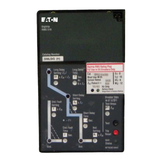
The Digitrip RMS 51 0, illustrated in Fig. 1 , is a custom
application specific integrated circuit based trip unit suit
able for use in types OS and DSL low voltag , e AC power
circuit breakers and type SPB Systems Pow-R circuit
.. . 15
breakers and Series
breakers.
The Digitrip RMS 5 10 provides true RMS current sensing
for proper correlation with thermal characteristics of con
ductors and equipment. Interchangeable rating plugs are
provided to establish the continuous current rating of
each circuit breaker.
A
WARNING
Send to
Call
Telep hone
FAX
Number
Number
(412) 937-6396
(412) 937-6029
(412) 937-6029
(412) 937-6396
(412) 937-6490
(412) 937-6010
c®
R-Frame molded case circuit
I.L. 29-8858
Advertisement
Table of Contents

Related Manuals for Eaton Cutler-Hammer Digitrip RMS 510 Trip Unit


Summary of Contents for Eaton Cutler-Hammer Digitrip RMS 510 Trip Unit
-
Page 1: Table Of Contents
Cutler-Hammer I.L. 29-8858 Instructions for Digitrip RMS 510 Trip Unit Table of Contents Page WARNING 1 . 0 General Description ....1 1 .1 Protection .... -
Page 2: Information
I.L. 29-8858 Page The Digitrip RMS 51 0 Trip Unit is completely self-con Note*: RMS Digitrip Type Ll, LS, and LSI trip u nits tained and when the circuit breaker is closed, requires can be applied on 3-pole or 4-pole circuit b reakers for the circuit breaker external control power to operate its protection sys... - Page 3 I. L. 29-885 8 Page Fig. 2. 1 Long Time/Instantaneous Protection (LI) Fig. 2.3 Long Time/Short Time/Instantaneous Protection (LSI) Long Time/Short Time Protection (LS) Fig. 2.2 Fig. 2.4 Long Time/Instantaneous/Ground Protec tion (LIG ) 1997 Effective May...
-
Page 4: Testing
I. L. 29-8858 Page �� �-- - Fig. 2.5 Long Time/Short Time/Ground/Protection Fig. 2.6 Long Time/Short Time/Instantaneous/Ground Protection (LSIG) (LSG) basic func Digitrip RMS 510 Trip unit provides three 1.3 Testing tions: typical trip Protection, Information and Testing. A test the Sec... -
Page 5: Trip And Operation Indicators
I.L. 29-8858 Page 5 ----- ----- ------- ----------- F lu ;,�:� � ::2�:�,::,�0 1 ;:�T1 ?, � �'[:' , � �u•l See Secuon 3 5 ']' ']' ']' ondoc3tesCause l"PUi l lt j. ; - -----_j tl loght�<l RED Op.erat•"9Stat u s Q!TRIPilocared SHSf'Won l ] Onf<omP;o,.ell... -
Page 6: Override (Fixed Instantaneous)
I.L. 29-8858 Page6 Notes : Note: If a breaker (M) receives a Zone Interlocking s ignal from another breaker (F), but the fault current This switch has eight (8) positions, and seven (7) level is less than the trip unit setting for breaker (M), of them show "DIS"... -
Page 7: Long Delay Current Settings
I.L. 29-8858 Page 7 4.2 Long Delay Current Setting allow for the fact that the load circuit temperature is already higher than normal, due to the prior There are eight (8) available Long Delay Settings, as overload condition. Each time an overload condi illustrated in Fig. -
Page 8: Short Delay Current Settings
I.L. 29-8858 PageS other two settings are "M1" or "M2" times (In)· The values LOT w il l reset itself. You can of course, manually clear the LOT (or any other trip indication) at any that "M1" and "M2" have depend upon the type of circuit time, by pushing the "PUSH to RESET"... -
Page 9: Ground Fault Current Settings
I.L. 29-8858 Page 9 TABL E 1 -GROUND FAULT CURRENT SETIINGS ------ Available Setti ngs 1...,. . 1 GROUND FAULT CURRENT SETTINGS ..3. 4, (AMPERES) 2. 2.5, • 5. 6, M,, M, lnst Setting ITJx In Multiples Rating Plug Amperes O n ) ®... -
Page 10: Test Procedure
I.L. 29-8858 Page 1 0 Breaker Trips <D At 6T and GFT "6T" =Phase Current Test at TRIPS brea k er; 6xl n and or 10" x I "1, 2. 3, 8 (ill CD Test Amps =Phase Gnd Fault � x 10 Time Current Test . -
Page 11: When To Test
I.L. 29-8858 Page 5.2 When To Test the current is not less than 1 0% of the breaker frame (or current sensor) rating; be Tests can be conducted with the breaker in the "con sure the "GR EEN" Unit Status LED (in the nected"... -
Page 12: Tripping The Breaker
I.L. 29-8858 Page the APM it may appear as if the trip unit does not trip u n it will not execute your instructions to Test respond until the current is well-above the set value, itself, when the load current exceeds 50% of leading the tester to believe there is an error in the Place the "Test Amps"... - Page 13 I.L. 29-8858 Page 13 obtained from the following companies under their type Note: The battery can be replaced at any time, even designation indicated: while the circuit breaker is in service, withou t affect ing the operation of the circuit breaker or its protec Company Model tion fu nction.
-
Page 14: Auxiliary Power Module
I.L. 29-8858 Page rent value (or "Sensor Rated", if applica 7.0 AUXILIA R Y POWER MODULE ble), The Auxiliary Power Module or APM (Cat No. and 2) "In (Rated I) =" current value. PRTAAPM), illustrated in Fig. 7, is an encapsulated power supply that requires a 120 Vac input at either 5 0 or This latter value, (In) is the basis for the trip unit current 60 Hz. -
Page 15: References
I.L. 29-8858 Page 1 5 9.0 REFERENCES I . L . 29C7 1 4 Master Con nection Diagram for Series c® R- Frame Circuit Brea ker 9.1 Digitrip RMS Trip Assemblies APPENDIX A ZONE INTERLOCKING I.L. 29-885 I nstru ctions for Digitrip AMS 5 1 0 Trip U nit Assume a ground fault of 2000 Amperes occurs and I . - Page 16 I.L. 29-8858 Page Notes: A1: Wiring to be twisted pair of AWG No. to AWG No. 20. Route Zone Interlocking wiring sepa- rate from power conductors. M a i n 3200 A DO NOT GROUND any Zone Interlock Wiring. 0.5 Sec The maximum distance between first 1 200 A and last zone is 250 feet (11 0 m).
- Page 17 I.L. 29-8858 Page NOTES 1997 Effective May...
- Page 18 I.L. 29-8858 Page NOTES 1997 Effective May...
- Page 19 I.L. 29-8858 Page 1 9 NOTES 1997 Effective May...
- Page 20 I.L. 29-8858 Page This instruction booklet is published solely for information purposes and should not be considered all inclusive. If further information is required, you should consult Cutler-Hammer. Sale of product shown in this literature is subject to terms and conditions outlined in appropriate Cutler-Hammer Inc.
Need help?
Do you have a question about the Cutler-Hammer Digitrip RMS 510 Trip Unit and is the answer not in the manual?
Questions and answers