Table of Contents
Advertisement
Quick Links
Advertisement
Table of Contents

Related Manuals for Eaton Managed ePDU


Summary of Contents for Eaton Managed ePDU
- Page 1 Managed ePDU User’s Guide...
- Page 2 Netscape Communication Corporation. All other trademarks are property of their respective companies. Copyright 2008 Eaton Corporation, Raleigh, NC, USA. All rights reserved. No part of this document may be reproduced in any way without the express written approval of Eaton Corporation.
- Page 3 Operation of this equipment in a residential environment may cause harmful interference. VCCI Information (Japan) Eaton is not responsible for damage to this product resulting from accident, disaster, misuse, abuse, non−Eaton modification of the product, or other events outside of Eaton’s reasonable control or not arising under normal operating conditions.
- Page 5 Null modem cable with RJ−45 and DB−9F connectors on either end 1U Models ePDU including power cord 1.80m (6 ft) 1U bracket pack and screws Null modem cable with RJ−45 and DB−9F connectors on either end EATON 1 DRAFT 10−OCT−2008 Managed ePDU User’s Guide 164201xxx Rev...
-
Page 6: Table Of Contents
................. EATON Managed ePDU 164201xxx Rev 1 DRAFT 10−OCT−2008... - Page 7 ..................EATON Managed ePDU 164201xxx Rev 1 DRAFT 10−OCT−2008...
- Page 8 ................EATON Managed ePDU 164201xxx Rev 1 DRAFT 10−OCT−2008...
- Page 9 ............. . . EATON Managed ePDU 164201xxx Rev 1 DRAFT 10−OCT−2008...
- Page 10 TABLE OF CONTENTS EATON Managed ePDU 164201xxx Rev 1 DRAFT 10−OCT−2008 User’s Guide...
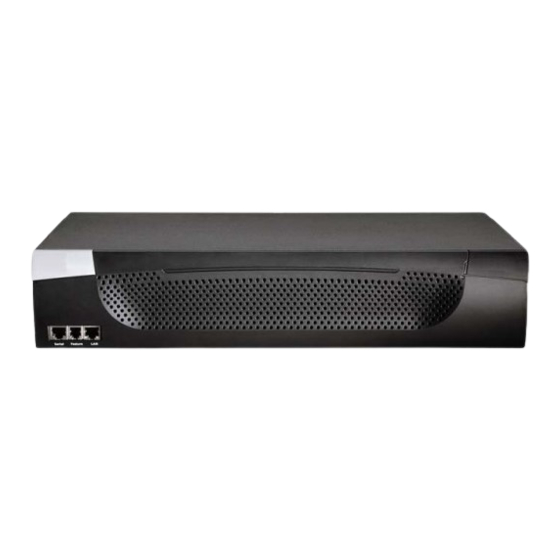
- Page 11 Models The ePDU comes in several models that are built to stock and can be obtained almost immediately. Eaton also offers custom models that are built to order and can only be obtained on request. ePDU Photos The ePDU models are available in three sizes: zero U (0U), 1U, and 2U (see Figure 1 through Figure 3).
- Page 12 INTRODUCTION Front Back Figure 2. 1U Size Front Back Figure 3. 2U Size EATON Managed ePDU 164201xxx Rev 1 DRAFT 10−OCT−2008 User’s Guide...
-
Page 13: Package Contents
Null modem cable with RJ−45 and DB−9F connectors on either end 1U Models ePDU including power cord 1.80m (6 ft) 1U bracket pack and screws Null modem cable with RJ−45 and DB−9F connectors on either end EATON Managed ePDU 164201xxx Rev 1 DRAFT 10−OCT−2008 User’s Guide... - Page 14 INTRODUCTION 2U Models ePDU including power cord 1.80m (6 ft) 2U bracket pack and screws Null modem cable with RJ−45 and DB−9F connectors on either end EATON Managed ePDU 164201xxx Rev 1 DRAFT 10−OCT−2008 User’s Guide...
- Page 15 ATTENTION: UTILISER UNIQUEMENT DANS DES EMPLACEMENTS SECS. W A R N I N G To avoid potentially fatal shock hazard and possible damage to Eaton equipment: Do not use a 2−wire power cord in any product configuration. Test AC outlets at your computer and monitor for proper polarity and grounding.
- Page 16 SAFETY WARNINGS EATON Managed ePDU 164201xxx Rev 1 DRAFT 10−OCT−2008 User’s Guide...
- Page 17 Rack−Mounting the ePDU Mount Safety Guidelines In Eaton products which require rack mounting, please follow these precautions: Operation temperature in a closed rack environment may be greater than 40°C . Do not exceed the rated maximum ambient temperature of the appliances (see Appendix E: Specifications).
- Page 18 NOTE For side and blind fixing: Do not repeatedly slide the bracket along the extrusion. This may degrade the support capability. For larger/heavier power strips more than one pair of clip fixings may be used. EATON Managed ePDU 164201xxx Rev 1 DRAFT 10−OCT−2008 User’s Guide...
- Page 19 Press the ePDU forward, pushing the silver buttons through the mounting holes, then letting the ePDU drop about 16 mm. This secures the ePDU in place and completes the installation. EATON 1 DRAFT 10−OCT−2008 Managed ePDU User’s Guide 164201xxx Rev...
- Page 20 RACK−MOUNTING THE EPDU EATON Managed ePDU 164201xxx Rev 1 DRAFT 10−OCT−2008 User’s Guide...
-
Page 21: Before You Begin
Inspect the equipment carefully. If any of the equipment is damaged or missing, contact your Eaton service representative for assistance. Prepare the Installation Site Make sure the installation area is clean and free of extreme temperatures and humidity. - Page 22 Figure 10. 1U ePDU Ports Serial Feature Figure 11. 2U ePDU Ports Plug the other end of the null modem cable (containing the DB−9 connector) into the serial port (COM) of the computer. EATON Managed ePDU 164201xxx Rev 1 DRAFT 10−OCT−2008 User’s Guide...
- Page 23 Point the communications program at the serial port connecting the ePDU and open a terminal window. Press Enter to display the opening configuration prompt (see Figure 12). Figure 12. Opening Configuration Prompt EATON 1 DRAFT 10−OCT−2008 Managed ePDU User’s Guide 164201xxx Rev...
- Page 24 NOTE If you accidentally create a rule that locks you out of the ePDU, you can rerun the configuration program and reset this parameter to disabled to allow you to access the ePDU. EATON Managed ePDU 164201xxx Rev 1 DRAFT 10−OCT−2008...
- Page 25 To keep the default, press Enter. To specify half or full duplex, type half or full and press Enter. You are prompted to confirm the information you just entered (see Figure 17). Figure 17. Confirmation Prompt EATON Managed ePDU 164201xxx Rev 1 DRAFT 10−OCT−2008 User’s Guide...
- Page 26 Figure 18. Configuration Complete NOTE The configured IP address takes about 15 seconds to take effect for the device connected through the serial line, or even longer if configured over DHCP. EATON Managed ePDU 164201xxx Rev 1 DRAFT 10−OCT−2008 User’s Guide...
-
Page 27: Resetting To Factory Defaults
NOTE Enter help to show a list of available commands and a short description of each one. Figure 19 shows the location of the reset hole for the 1U and 2U models. Figure 20 shows the reset hole for the 0U model. EATON Managed ePDU 164201xxx Rev 1 DRAFT 10−OCT−2008 User’s Guide... - Page 28 INSTALLATION AND CONFIGURATION Reset Hole Figure 19. Reset Hole (1U and 2U Models) Reset Hole Figure 20. Reset Hole (0U Models) EATON Managed ePDU 164201xxx Rev 1 DRAFT 10−OCT−2008 User’s Guide...
-
Page 29: Front Panel
DB−9F connector to the serial (COM) port on the computer. Feature For use with Eaton−provided environmental sensors. Connecting the ePDU to your company’s network. Connect a standard Category 5e UTP cable to this port and connect the other end to your network. -
Page 30: Power Cord
LEDs cycle through red, green and yellow. When the software has completed loading, the outlet LEDs displays a steady color and the meter illuminates. EATON Managed ePDU 164201xxx Rev 1 DRAFT 10−OCT−2008 User’s Guide... - Page 31 Voltage has no decimal point, current has a decimal point between the first and second digits, and power has a decimal point between the second and third digits. EATON Managed ePDU 164201xxx Rev 1 DRAFT 10−OCT−2008...
- Page 32 It takes a maximum of three seconds for the beeper to start ringing after the circuit breaker has been tripped. Accuracy Voltage (per outlet): Range 0–255V, ± 5%, 3 digits, resolution 1V Current (per outlet): Range 0–25.5A, ± 5%, 3 digits, resolution 0.1A EATON 1 DRAFT 10−OCT−2008 Managed ePDU User’s Guide 164201xxx Rev...
-
Page 33: Using The Web Interface
Figure 22. Login Page Type your user name and password in the Username and Password fields. Both the user name and password are case−sensitive, so make sure you capitalize the letters correctly. EATON Managed ePDU 164201xxx Rev 1 DRAFT 10−OCT−2008 User’s Guide... - Page 34 Web browser for proper operation. If JavaScript is not enabled, features such as the Status Panel on the left side of the interface will not display correctly. EATON Managed ePDU 164201xxx Rev 1 DRAFT 10−OCT−2008...
-
Page 35: Changing Your Password
Every page in the Web interface provides menus and a navigation path across the top, and a status panel to the left. Menus There are several menus in the Web interface: Power Outlets Alerts User Management Device Settings Maintenance Outlet Groups EATON Managed ePDU 164201xxx Rev 1 DRAFT 10−OCT−2008 User’s Guide... -
Page 36: Navigation Path
To return to a previous page, click the page name in the navigation path. Every navigation path begins at the Home page, so a single click always takes you back to the Home page from anywhere in the interface. EATON Managed ePDU 164201xxx Rev 1 DRAFT 10−OCT−2008 User’s Guide... -
Page 37: Status Panel
− IP address − Current state Your current session is included in this list. A link to the User’s Guide on the Eaton Web site. ePDU Figure 27. Status Panel The State field in the user information section considers a user to be idle 30 seconds after the last keyboard or mouse action. -
Page 38: Status Messages
For example: if you select the Admin User Group in Internet Explorer, the buttons for Copy, Modify and Delete will be dimmed since you cannot Copy, Modify or Delete the Admin user group. In Firefox, however, these non−functioning buttons display normally. EATON Managed ePDU 164201xxx Rev 1 DRAFT 10−OCT−2008 User’s Guide... -
Page 39: Reset To Defaults
You can return to the Home page from any other page in the Web interface by clicking: The Home link in the navigation path The Eaton logo above the Status panel Model name under the logo Global Status Panel The Global Status panel provides an overview of the ePDU’s power consumption and temperature. -
Page 40: Outlets List
Outlet Details page (see Figure 54 on page 58). This page gives the name and status of the outlet, as well as: RMS Current Maximum RMS Current RMS Voltage Active Power Apparent Power Power Factor EATON 1 DRAFT 10−OCT−2008 Managed ePDU User’s Guide 164201xxx Rev... -
Page 41: All Outlets Control
You can change this so only one user at a time can use a specific login. This is done by selecting Device Settings > Security and selecting the Enable Single Login Limitation check box. EATON Managed ePDU 164201xxx Rev 1 DRAFT 10−OCT−2008... -
Page 42: Creating A User Profile
An email address where the user can be reached. Mobile Number A cell phone number where the user can be reached. NOTE The New User Name, Password, and Confirm Password are the only required fields. EATON Managed ePDU 164201xxx Rev 1 DRAFT 10−OCT−2008 User’s Guide... -
Page 43: Copying A User Profile
Password and Confirm Password fields. If the password field is left blank, the password is not changed. Click Modify. The user profile is modified. EATON Managed ePDU 164201xxx Rev 1 DRAFT 10−OCT−2008 User’s Guide... -
Page 44: Deleting A User Profile
This means that if you do not change the entry in this field, the user will enjoy full system and outlet permissions. To restrict the user’s permissions, create a user group with limited system and/or outlet permissions, and assign the user to that group. EATON Managed ePDU 164201xxx Rev 1 DRAFT 10−OCT−2008 User’s Guide... -
Page 45: Creating A User Group
Figure 36. User Group Management page − Group Management Panel In the Group Management panel, type the name of the group in the New Group Name field. Click Create. The user group is created. EATON Managed ePDU 164201xxx Rev 1 DRAFT 10−OCT−2008 User’s Guide... -
Page 46: Setting System Permissions
Set the permissions as necessary. Click this icon in a field and select either Yes or No. When you are finished, click Apply. The permissions are applied to the user group. EATON Managed ePDU 164201xxx Rev 1 DRAFT 10−OCT−2008 User’s Guide... -
Page 47: Setting The Outlet Permissions
To set the outlet permissions for a user group: Select , and then select . The User Management Users/Group Outlet Permissions User/Group Outlet Permissions page displays (see Figure 38). Figure 38. User/Group Outlet Permissions Page EATON Managed ePDU 164201xxx Rev 1 DRAFT 10−OCT−2008 User’s Guide... -
Page 48: Copying A User Group
Click Modify. The user group is modified. NOTE To modify a user group’s system or outlet permissions, repeat the procedure for setting the system or outlet permissions described above and make any necessary changes. EATON Managed ePDU 164201xxx Rev 1 DRAFT 10−OCT−2008 User’s Guide... -
Page 49: Deleting A User Group
NOTE The purpose of disabling the firewall by default is to prevent users from accidentally locking themselves out of the ePDU. See Chapter 4, Installation and Configuration," for details. EATON Managed ePDU 164201xxx Rev 1 DRAFT 10−OCT−2008 User’s Guide... -
Page 50: Enabling The Firewall
The default policy is shown in the Default Policy field (see Figure 40). To change it, select the policy you want from the drop−down list in the field. Click Apply. The new default policy is applied. EATON Managed ePDU 164201xxx Rev 1 DRAFT 10−OCT−2008 User’s Guide... -
Page 51: Creating Firewall Rules
S Type an IP address and subnet mask in the IP/Mask field. S Select ACCEPT or DROP from the drop−down list in the Policy field. S Click Replace. This system replaces the existing rule with the one you just created. EATON Managed ePDU 164201xxx Rev 1 DRAFT 10−OCT−2008 User’s Guide... -
Page 52: Deleting A Firewall Rule
User group. Finally, you have to indicate whether the rule will accept or drop traffic. Changes made do not affect users currently logged in until the next login. EATON Managed ePDU 164201xxx Rev 1 DRAFT 10−OCT−2008 User’s Guide... -
Page 53: Enabling Group−Based Access Control Rules
Select the Enable Group based System Access Control check box if it is not already selected. Select the action you want from the Default Action list in the (see Figure 42). Click Apply. The default action is applied. EATON Managed ePDU 164201xxx Rev 1 DRAFT 10−OCT−2008 User’s Guide... -
Page 54: Creating Group−Based Access Control Rules
Type the number of the rule to be deleted in the Rule # field. Click Delete. The rule is removed from the Group Based System Access Control panel. Click Apply. The rule is deleted. EATON Managed ePDU 164201xxx Rev 1 DRAFT 10−OCT−2008 User’s Guide... -
Page 55: Setting Up User Login Controls
If no number is entered, there is no limit on failed logins. Type a number in the Block time field. This is the length of time in minutes the login is blocked. Click Apply. The user blocking limits are applied. EATON Managed ePDU 164201xxx Rev 1 DRAFT 10−OCT−2008 User’s Guide... -
Page 56: Enabling Login Limitations
Aging check box, and then enter a number of days in the Password Aging Interval field. Users will be required to change their password every time that number of days has passed. Click Apply. The controls are applied. EATON Managed ePDU 164201xxx Rev 1 DRAFT 10−OCT−2008 User’s Guide... -
Page 57: Enabling Strong Passwords
Required At least one printable special character Required Number of restricted passwords Make any necessary changes to the default settings. When you are finished, click Apply. The changes are applied. EATON Managed ePDU 164201xxx Rev 1 DRAFT 10−OCT−2008 User’s Guide... -
Page 58: Setting Up A Digital Certificate
To create a CSR: Select Device Settings, and then select Certificate. The first page of the SSL Server Certificate Management page displays (see Figure 47). Figure 46. SSL Server Certificate Signing (First Page) EATON Managed ePDU 164201xxx Rev 1 DRAFT 10−OCT−2008 User’s Guide... - Page 59 The file is called csr.txt. Once the file is stored on your computer, submit it to a CA to obtain the digital certificate. EATON Managed ePDU 164201xxx Rev 1 DRAFT 10−OCT−2008 User’s Guide...
-
Page 60: Installing A Certificate
Keep in mind that you still need to create user profiles for users who are authenticated externally. This is because the user profile determines the user group to which the user belongs, and the user group determines the user’s system and outlet permissions. EATON Managed ePDU 164201xxx Rev 1 DRAFT 10−OCT−2008 User’s Guide... -
Page 61: Setting Up Ldap Authentication
Type the base distinguish name (DN) in the Base DN of User LDAP Server field. The DN base is the top level of the LDAP directory tree. It indicates where in the LDAP directory you want to begin searching for user credentials. EATON Managed ePDU 164201xxx Rev 1 DRAFT 10−OCT−2008 User’s Guide... -
Page 62: Setting Up Radius Authentication
RADIUS server. By default, the ePDU uses the standard RADIUS ports 1812 (authentication) and 1813 (accounting). If you prefer to use non−standard ports, change the ports. EATON Managed ePDU 164201xxx Rev 1 DRAFT 10−OCT−2008 User’s Guide... -
Page 63: Setting Up Outlets And Power Thresholds
When setting the thresholds, keep in mind that you can set up alerts that are triggered whenever any of these thresholds are crossed. See Setting Up Alerts" on page 62 for details. EATON Managed ePDU 164201xxx Rev 1 DRAFT 10−OCT−2008 User’s Guide... -
Page 64: Setting Default Outlet State
Select Device Settings, and then select Unit Setup. The Unit Setup page displays. Figure 50. Unit Setup Page Select the default state from the Default outlet state on device startup list. Click Apply. The default state is set. EATON Managed ePDU 164201xxx Rev 1 DRAFT 10−OCT−2008 User’s Guide... -
Page 65: Setting The Epdu Thresholds
Set the RMS voltage, current, and temperature thresholds for the ePDU in the Thresholds panel. For each setting, enter critical and non−critical thresholds. Click Apply. The delays and thresholds are applied. EATON Managed ePDU 164201xxx Rev 1 DRAFT 10−OCT−2008 User’s Guide... -
Page 66: Setting The Outlet Power−Up Sequence
NOTE If you use Outlet Grouping to group outlets together, you should adjust the Outlet Sequencing to ensure that all outlets from this ePDU, that are part of the same group, power up consecutively. EATON Managed ePDU 164201xxx Rev 1 DRAFT 10−OCT−2008... -
Page 67: Naming Outlets
ON or OFF when the ePDU powers up. If set to Device Default, the state for this outlet will be determined by the Default Outlet State in the Unit Setup page (see page 54). Click Apply to save your changes. EATON Managed ePDU 164201xxx Rev 1 DRAFT 10−OCT−2008 User’s Guide... -
Page 68: Setting Outlet Thresholds
Viewing Outlet Details To display details about a particular outlet: Select Power Outlet and then select Outlet Details. The Outlet Details page displays (see Figure 54). Figure 54. Outlet Details Page EATON Managed ePDU 164201xxx Rev 1 DRAFT 10−OCT−2008 User’s Guide... -
Page 69: Power Cycling An Outlet
Select an outlet from the Show details of outlet list. Click On to turn the outlet ON. Click Off to turn the outlet OFF. NOTE You can also turn an outlet on or off from the Home page. EATON Managed ePDU 164201xxx Rev 1 DRAFT 10−OCT−2008 User’s Guide... -
Page 70: Environmental Sensors
Temperature Sensors table, humidity sensors in the Environmental Humidity Sensors table. If the sensors are not attached properly, the page will state that No sensors were detected. Figure 55. Environmental Sensors Page EATON Managed ePDU 164201xxx Rev 1 DRAFT 10−OCT−2008 User’s Guide... -
Page 71: Configuring Environmental Sensors And Thresholds
Once critical, the temperature or humidity must drop below the Upper Non−Critical (or raise above the Lower Non−Critical) value before the ePDU considers the environment to be acceptable again. Click Apply to save the settings. EATON Managed ePDU 164201xxx Rev 1 DRAFT 10−OCT−2008 User’s Guide... -
Page 72: Viewing Sensor Readings
Select the outlet from the first list under Event. You can select the ePDU as a whole or you can select a specific outlet. You can also select an individual relay board, the Environmental Temperature Sensors or the Environmental Humidity Sensors. EATON Managed ePDU 164201xxx Rev 1 DRAFT 10−OCT−2008 User’s Guide... -
Page 73: Creating Alert Policies
SNMP trap, a selected outlet to be switched on/off/cycled, or any combination of the four. EATON Managed ePDU 164201xxx Rev 1 DRAFT 10−OCT−2008 User’s Guide... -
Page 74: About Policies
You can modify or delete a policy by clicking the corresponding button next to the policy. You can add a new policy and configure alerts and destinations by clicking the appropriate link. EATON Managed ePDU 164201xxx Rev 1 DRAFT 10−OCT−2008 User’s Guide... -
Page 75: Create A Policy
USING THE WEB INTERFACE Create a Policy To create a policy: Select Alerts, and then select Alert Policy Editor. The Alert Policy Editor displays (see Figure 61). Figure 61. Alert Policy Editor EATON Managed ePDU 164201xxx Rev 1 DRAFT 10−OCT−2008 User’s Guide... -
Page 76: Modify A Policy
Select Alerts, and then select Alert Policy Editor. The Alert Policy Editor displays. Select the policy to be deleted from the Existing Policies list. Click Delete. The policy is deleted. NOTE The default alert policy System Event Log" cannot be deleted. EATON Managed ePDU 164201xxx Rev 1 DRAFT 10−OCT−2008 User’s Guide... -
Page 77: Specifying The Alert Destination
SNMP. If you selected SNMP, enter the IP address of the trap and the community string. Click Add. The destination is added. To delete an alert destination, click the appropriate Delete button. EATON Managed ePDU 164201xxx Rev 1 DRAFT 10−OCT−2008 User’s Guide... -
Page 78: Setting Up Event Logging
Click the Clear button. The button changes to Really Clear and you are prompted to click it only if you are certain you want to clear the log. Click Really Clear to complete the clear operation, or click Cancel to terminate EATON Managed ePDU 164201xxx Rev 1 DRAFT 10−OCT−2008 User’s Guide... - Page 79 See Figure 64. Figure 64. Event Log Assignments Panel (List Logging) NOTE See Chapter 10, Appendix B, Event Types" for a more detailed explanation. Click Apply. Local logging is configured. EATON Managed ePDU 164201xxx Rev 1 DRAFT 10−OCT−2008 User’s Guide...
-
Page 80: Viewing The Internal Event Log
IP address of the user’s computer. NOTE By default, the internal event log displays 20 events per page. See Configuring the Local Event Log" on page 68 for instructions on changing this number. EATON Managed ePDU 164201xxx Rev 1 DRAFT 10−OCT−2008 User’s Guide... -
Page 81: Configuring Nfs Logging
Event Log Assignments panel to the right. All are disabled by default. To enable any of these event types, select the corresponding check boxes. See Figure 67. Figure 67. Event Log Assignments Panel (List and NFS Logging) Click Apply. NFS logging is configured. EATON Managed ePDU 164201xxx Rev 1 DRAFT 10−OCT−2008 User’s Guide... -
Page 82: Configuring Smtp Logging
NOTE If you have not configured the ePDU SMTP settings, you must do so for SMTP logging to work. Click the here link at the bottom of the panel. See Configuring the SMTP Settings" on page 80 for instructions. EATON Managed ePDU 164201xxx Rev 1 DRAFT 10−OCT−2008... -
Page 83: Configuring Snmp Logging
Event Log Assignments panel to the right. All are disabled by default. To enable any of these event types, select the appropriate check boxes. See Figure 71. Figure 71. Event Log Assignments Panel Click Apply. Syslog Forwarding is configured. EATON Managed ePDU 164201xxx Rev 1 DRAFT 10−OCT−2008 User’s Guide... -
Page 84: Managing The Epdu
Figure 72. Device Information Page To open or save an XML file providing details for Eaton Technical Support, click the View the datafile for support link. EATON Managed ePDU 164201xxx Rev 1 DRAFT 10−OCT−2008... -
Page 85: Displaying Model Configuration
Select Device Settings, and then select Network. The Network Settings page displays. The left side of the page consists of the Basic Network Settings panel, which contains the device name. See Figure 73. Figure 73. Basic Network Settings Panel EATON Managed ePDU 164201xxx Rev 1 DRAFT 10−OCT−2008 User’s Guide... -
Page 86: Modifying The Network Settings
Static IP: To enter a static IP address, select None from the IP Auto Configuration list, and then enter: IP address Subnet mask Gateway address Primary and (optional) secondary DNS server addresses Click Apply. The network settings are modified. EATON Managed ePDU 164201xxx Rev 1 DRAFT 10−OCT−2008 User’s Guide... -
Page 87: Modifying The Communications, Port, And Bandwidth Settings
You can change this and enable or disable either application. You can also set a bandwidth limit, and change any of the default port settings. Finally, you can enable or disable the Eaton Setup Protocol. To do this: Select Device Settings, and then select Network. -
Page 88: Modifying The Lan Interface Settings
Half duplex allows data to be transmitted to and from the ePDU, but not at the same time. Full duplex allows data to be transmitted in both directions at the same time. Click Apply. The settings are modified. EATON Managed ePDU 164201xxx Rev 1 DRAFT 10−OCT−2008 User’s Guide... -
Page 89: Setting The Date And Time
NOTE If the ePDU’s IP address is assigned through DHCP, the NTP server addresses will be automatically discovered, then users will not be able to enter any data in the fields of primary and secondary time server. Click Apply. The date and time settings are applied. EATON Managed ePDU 164201xxx Rev 1 DRAFT 10−OCT−2008 User’s Guide... -
Page 90: Configuring The Smtp Settings
Address field and click Send. NOTE Do not test the SMTP settings until you have first applied them. If you do, you will lose the settings and be forced to re−enter them. EATON Managed ePDU 164201xxx Rev 1 DRAFT 10−OCT−2008 User’s Guide... -
Page 91: Configuring The Snmp Settings
Click the link at the bottom of the page to download an SNMP MIB for your ePDU to use with your SNMP manager. 10. Click Apply. The SNMP configuration is set. EATON Managed ePDU 164201xxx Rev 1 DRAFT 10−OCT−2008 User’s Guide... -
Page 92: Resetting The Epdu
The reset takes about one minute to complete. See Figure 81. Figure 81. Reset Conclusion Page When the reset is complete, the Login page displays, and you can log back into the ePDU. EATON Managed ePDU 164201xxx Rev 1 DRAFT 10−OCT−2008 User’s Guide... -
Page 93: Updating The Firmware
USING THE WEB INTERFACE Updating the Firmware Eaton will notify customers when new firmware is available to update the ePDU. Customers will be given instructions where to go to download the new firmware. Once the firmware is downloaded onto a PC, you can install it on the ePDU from the Web interface. -
Page 94: Outlet Grouping
To add outlets from other ePDUs, you must first identify which ePDU will be sharing their outlets. To do this: Select Outlet Groups, and then select Outlet Group Devices. The Outlet Group Devices page displays. Figure 85. Outlet Group Devices Page EATON Managed ePDU 164201xxx Rev 1 DRAFT 10−OCT−2008 User’s Guide... -
Page 95: Grouping Outlets Together
Create. NOTE You should not add a physical outlet to more than one outlet group. Click Create. The outlet group is created and added to the Outlet Groups list. EATON Managed ePDU 164201xxx Rev 1 DRAFT 10−OCT−2008 User’s Guide... -
Page 96: Controlling Outlet Groups
To view or edit the composition of an outlet group, click on the name of the outlet group in the list to go to the Outlet Group Editor for the selected outlet group. EATON Managed ePDU 164201xxx Rev 1 DRAFT 10−OCT−2008 User’s Guide... -
Page 97: Editing Or Deleting Outlet Groups
(the ePDU you are currently accessing) from the Outlet Group Devices list. If you do, you can add it back to the list using the IP address 127.0.0.1. EATON Managed ePDU 164201xxx Rev 1 DRAFT 10−OCT−2008... - Page 98 USING THE WEB INTERFACE EATON Managed ePDU 164201xxx Rev 1 DRAFT 10−OCT−2008 User’s Guide...
-
Page 99: Using The Clp Interface
Launch HyperTerminal and open a console window. When the window first opens, it is blank. Press Enter to display a Command prompt (see Figure 88). Figure 88. HyperTerminal Command Prompt EATON Managed ePDU 164201xxx Rev 1 DRAFT 10−OCT−2008 User’s Guide... - Page 100 Once the password is accepted, the clp:/−> system prompt appears. See Figure 91. Figure 91. System Prompt You are now logged into the CLP interface and can begin using the interface to administer the ePDU. EATON Managed ePDU 164201xxx Rev 1 DRAFT 10−OCT−2008 User’s Guide...
-
Page 101: Using Ssh Or Telnet
Once the password is accepted, the clp:/−> system prompt appears. See Figure 94. Figure 94. System Prompt You are now logged into the CLP interface and can begin using the interface to administer the ePDU. EATON Managed ePDU 164201xxx Rev 1 DRAFT 10−OCT−2008 User’s Guide... -
Page 102: Showing Outlet Information
(*). Examples Figure 95 shows an example of the output when a show command is entered without attributes. Figure 95. Example 1 – No Attributes EATON Managed ePDU 164201xxx Rev 1 DRAFT 10−OCT−2008 User’s Guide... -
Page 103: Turning An Outlet On Or Off
Querying an Outlet Sensor The show command with the Antecedent key word queries the outlet sensors clp:/−> Show –d properties=Antecedent system1/<outlet number>=> AssociatedSensor where <outlet number> is the number of the outlet. EATON Managed ePDU 164201xxx Rev 1 DRAFT 10−OCT−2008 User’s Guide... - Page 104 USING THE CLP INTERFACE EATON Managed ePDU 164201xxx Rev 1 DRAFT 10−OCT−2008 User’s Guide...
-
Page 105: Using The Ipmi Tool Set
The IPMI level assigned determines what information can be viewed and what LAN configuration parameters can be set. Table 7 lists what functions are allowed for each IPMI privilege level. EATON Managed ePDU 164201xxx Rev 1 DRAFT 10−OCT−2008 User’s Guide... -
Page 106: Info [Channel Number]
$ ipmitool −I lan −H test−pdupcr20−20 −U admin −P pass channel setaccess 14 63 setaccess <channel number> <userid>[callin=on|off] [ipmi=on|off] [link=on|off] [privilege=level] Purpose: Configures user access information on the given channel for the given userid. Example: EATON Managed ePDU 164201xxx Rev 1 DRAFT 10−OCT−2008 User’s Guide... -
Page 107: Getciphers
NOTE The Event DIR/Type field is encoded with the event direction as the high bit (bit 7) and the event type as the low 7 bits. Example: 0x4 0x2 0x60 0x1 0x52 0x0 0x0 # Voltage threshold: Lower Critical: Going Low EATON Managed ePDU 164201xxx Rev 1 DRAFT 10−OCT−2008 User’s Guide...[Channel] -
Page 108: Lan Commands
S bios (address loaded by BIOS or system software) arp respond <on|off> Sets generated ARP responses arp generate <on|off> Sets generated gratuitous ARPs arp interval <seconds> Sets generated gratuitous ARP interval EATON Managed ePDU 164201xxx Rev 1 DRAFT 10−OCT−2008 User’s Guide... -
Page 109: Sensor Commands
$ ipmitool −I lan −H test−pdupcr20−20 −U admin −a sensor list get 0 [<id>] Purpose: Prints information for sensors specified by name. Example: $ ipmitool −I lan −H test−pdupcr20−20 −U admin −P pass sensor get “R.14 Current” EATON Managed ePDU 164201xxx Rev 1 DRAFT 10−OCT−2008 User’s Guide... -
Page 110: Thresh
Get Group Power On Delay 0x18 Set Socket ACL 0x19 Get Socket ACL 0x1A Set Sensor Calibration 0x1B Test Actors 0x1C Test Sensors 0x1D Set Power Cycle Delay 0x1E Get Power Cycle Delay 0x1F EATON Managed ePDU 164201xxx Rev 1 DRAFT 10−OCT−2008 User’s Guide... -
Page 111: Set Power Set Delay Command
[2] 1b = in power cycle delay phase, 0b = not delayed [1] 1b = released because of soft breaker, 0b = norm [0] 1b = power on, 0b = power off EATON Managed ePDU 164201xxx Rev 1 DRAFT 10−OCT−2008 User’s Guide... -
Page 112: Set Group State Command
… [0] 1b = socket 8 belongs to group [7] 1b = socket 23 belongs to group … [0] 1b = socket 16 belongs to group Response Data Completion Code EATON Managed ePDU 164201xxx Rev 1 DRAFT 10−OCT−2008 User’s Guide... -
Page 113: Get Group Membership Command
Response Data Completion Code Get Group Power On Delay Command Request Data Group number [7–5] reserved [4–0] group number, valid numbers: 0–23 Response Data Completion Code Delay in 1/10 seconds EATON Managed ePDU 164201xxx Rev 1 DRAFT 10−OCT−2008 User’s Guide... -
Page 114: Set Socket Acl
Used for hardware testing during production. Request Data [7–2] reserved [1] Beeper test, 0b = disable, 1b = enable [0] 7 segment display test, 0b = disable, 1b = enable Response Data Completion Code EATON Managed ePDU 164201xxx Rev 1 DRAFT 10−OCT−2008 User’s Guide... -
Page 115: Test Sensors
Completion Code Get Power Cycle Delay Command Request Data Socket number (0xFF for the global unit delay) Response Data Completion Code Delay (seconds), 1–255, 0 if not set (socket only) EATON Managed ePDU 164201xxx Rev 1 DRAFT 10−OCT−2008 User’s Guide... - Page 116 USING THE IPMI TOOL SET EATON Managed ePDU 164201xxx Rev 1 DRAFT 10−OCT−2008 User’s Guide...
-
Page 117: Appendix A: Equipment Setup Worksheet
Model Serial Number Outlet 10 Outlet 11 Outlet 12 Model Serial Number Outlet 13 Outlet 14 Outlet 15 Model Serial Number Outlet 16 Outlet 17 Outlet 18 Model Serial Number EATON Managed ePDU 164201xxx Rev 1 DRAFT 10−OCT−2008 User’s Guide... - Page 118 APPENDIX A: EQUIPMENT SETUP WORKSHEET Outlet 19 Outlet 20 Model Serial Number Types of adapters ____________________________________________________________________________________ Types of cables ____________________________________________________________________________________ Name of software program ____________________________________________________________________________________ EATON Managed ePDU 164201xxx Rev 1 DRAFT 10−OCT−2008 User’s Guide...
-
Page 119: Appendix B: Event Types
Entries with an IP address of 127.0.0.1 (the loopback IP address) represent a serial connection and a CLP session. Device Operation Device successfully started Device Management The Device update has started Virtual Device Management Master PDU lost connectivity with SlaveIPAddress EATON Managed ePDU 164201xxx Rev 1 DRAFT 10−OCT−2008 User’s Guide... - Page 120 APPENDIX B: EVENT TYPES EATON Managed ePDU 164201xxx Rev 1 DRAFT 10−OCT−2008 User’s Guide...
-
Page 121: Appendix C: Using Snmp
Select Enable SNMP v3 Protocol check box to enable communication with an SNMP manager using SNMP v3 protocol. Select the Force Encryption check box to force using encrypted SNMP communication. Then type: EATON Managed ePDU 164201xxx Rev 1 DRAFT 10−OCT−2008 User’s Guide... -
Page 122: Configuring Users For Encrypted Snmp V3
If you want to use the user’s password as their Encryption Phrase select the Use Password as Encryption Phrase check box if it not already selected. If you want to specify a different encryption phrase do the following: EATON Managed ePDU 164201xxx Rev 1 DRAFT 10−OCT−2008 User’s Guide... -
Page 123: Configuring Snmp Traps
When SNMP logging is enabled, seven event types display in the Event Log Assignments panel to the right. All are disabled by default. To enable any of these event types, select the appropriate check boxes. EATON Managed ePDU 164201xxx Rev 1 DRAFT 10−OCT−2008 User’s Guide... - Page 124 Click Apply. SNMP logging is configured. NOTE Re−download the ePDU MIB after updating the ePDU firmware. This will ensure your SNMP manager has the correct MIB for the release you are using. EATON Managed ePDU 164201xxx Rev 1 DRAFT 10−OCT−2008 User’s Guide...
-
Page 125: Snmp Gets And Sets
(and send an SNMP trap) when certain parameters are exceeded. See Setting Up Outlets and Power Thresholds" section on page 53 in Chapter 6, Using the Web interface" for a description of how thresholds work. EATON Managed ePDU 164201xxx Rev 1 DRAFT 10−OCT−2008 User’s Guide... - Page 126 Table 11. RJ−11 PIN/Signal Definition Pin No. Signal Direction Description Power (500mA, fuse−protected) Signal Ground RS485 (Data +) bidirectional Data Line + RS485 (Data −) bidirectional Data Line − Signal Ground 1−wire EATON Managed ePDU 164201xxx Rev 1 DRAFT 10−OCT−2008 User’s Guide...
-
Page 127: Appendix D: Specifications
APPENDIX D: SPECIFICATIONS EATON Managed ePDU 164201xxx Rev 1 DRAFT 10−OCT−2008 User’s Guide... - Page 129 *164201xxx1* 164201xxx 1...
Need help?
Do you have a question about the Managed ePDU and is the answer not in the manual?
Questions and answers