Table of Contents
Advertisement
Quick Links
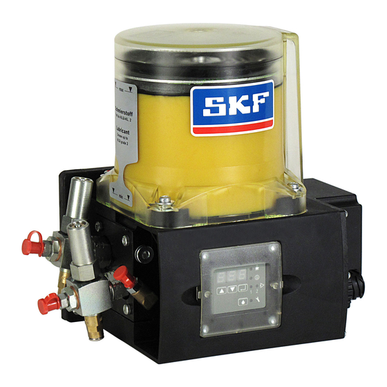
Piston pump unit with reservoir
for use in centralized lubrication systems
Product series:
KFA1-.., KFA10-..
KFAS1-.., KFAS10-..
WARNING:
Read this owner's manual before installing, operating or maintaining the product. Failure to follow the
instructions and safety precautions in this owner's manual could result in serious injury, death, or property
damage. Keep for future reference.
Owner's Manual - Containing Installation,
Operation and Maintenance Instructions
(Original installation instructions in accordance with EC-
Machinery Directive 2006/42/EC)
Version 05
Advertisement
Table of Contents

Related Manuals for SKF KFA1 series


Summary of Contents for SKF KFA1 series
- Page 1 Owner’s Manual - Containing Installation, Piston pump unit with reservoir Operation and Maintenance Instructions for use in centralized lubrication systems (Original installation instructions in accordance with EC- Machinery Directive 2006/42/EC) Product series: Version 05 KFA1-.., KFA10-.. KFAS1-.., KFAS10-.. WARNING: Read this owner's manual before installing, operating or maintaining the product. Failure to follow the instructions and safety precautions in this owner’s manual could result in serious injury, death, or property damage.
-
Page 2: Masthead
Germany carriers, and data networks is strictly prohibited Tel. +49 (0)62 05 27-0 without the express permission of SKF Lubrication Fax +49 (0)62 05 27-101 Systems Germany GmbH . lubrication-germany@skf.com SKF Lubrication Systems Germany GmbH reserves www.skf.com/lubrication... -
Page 3: Table Of Contents
Table of contents Page 3 3.5.1. Modes of operation ....... 14 5.3.2. Storage of electronic and electrical Table of contents 3.5.2. Contact time (pump cycle time) ..14 devices ............. 31 Owner’s Manual - Containing Installation, 3.5.3. Interval time ........... 14 5.3.3. -
Page 4: Information Concerning Ec Declaration Of Incorporation
Due to its performance characteristics, the product forth in the EC Directive 2006/42/EC. does not reach the limit values defined in Article 4, SKF herewith certifies that it conforms to the Paragraph 1, Subparagraph (a) item (i) and is, pertinent safety requirements set forth in the... -
Page 5: General Information
General information Page 5 General information Instructions attached directly to the equipment, such Read this Owner's Manual before installing, oper- Explanation of symbols and signs as rotational direction arrows and fluid connection ating or maintaining the product. Failure to follow You will find these symbols, which warn of specific labels, must be followed. -
Page 6: Safety Instructions
CLP Regulation occur. The described product is manufactured in EC 1272/2008 may only be used to fill SKF accordance with the generally accepted rules and centralized lubrication systems and components and A definition of what constitutes a qualified person... -
Page 7: Electric Shock Hazard
1.5. Warranty and liability Electrical connections for the described product may SKF Lubrication Systems Germany GmbH assumes only be established by qualified and trained no warranty or liability for the following: personnel authorized to do so by the operator, and... -
Page 8: Lubricants
You can request an overview of the lubricant tests not receive adequate lubrication, which can and components after consulting with and obtaining offered by SKF Lubrication Systems Germany GmbH written approval from SKF Lubrication Systems lead to damage and failure of the bearing. -
Page 9: Approved Lubricants
2. Lubricants Page 9 Lubricant leaking from centralized lubrication 2.4. Lubricants and the environment systems is a serious hazard. Leaking lubricant can 2.3. Approved lubricants Warning! create risks that may result in physical harm to Warning! Lubricants can contaminate soil and bodies persons or damage to other material assets. -
Page 10: Design And Function
3. Design and function Page 10 Table 4 Model designs 3. Design and function Application Description Monitoring Control Mounted 3.1. Area of application and design manifold Fill level Cycle switch External Internal • The piston pump units with reservoir described here Commercial KFA1 •... - Page 11 3. Design and function Page 11 KFA1 KFAS1 Fig. 1. Piston pump units with reservoir, series KFA1 and KFAS1 Lubricant reservoir Lubricant outlet 1 Control screen Pump housing Filler socket Mounting flange Pressure regulating valve Lubricant outlet 2 (with pump element on KFAS1) Electrical connections...
-
Page 12: Pump Elements
Fig.2. Pump element with O-ring (item 1) lubrication system. request the documentation directly from SKF Lubrication Systems Germany GmbH . Table 5. Available pump elements Model designs with progressive distributors (3- to 9-port) mounted on the pump housing feed the Order No. -
Page 13: Pressure Regulating Valve
120 5 161-210-042 If no documentation is available, you can request the documentation directly from SKF Lubrication Systems Germany GmbH . Fig.4. Pressure regulating valve with T connector Connection for lubricant line Lubricant leakage on malfunction... -
Page 14: Fill Level Monitoring
3. Design and function Page 14 On piston pump units with integrated control adjustable number of pulses from an external pulse 3.4. Fill level monitoring unit, the operational sequence is stopped and a generator. 3.4.1. Visual fill level monitoring fault message appears on the control screen. Connect an external pulse generator to Danger! On piston pump units without control unit, the... -
Page 15: Progressive Distributor Monitoring
3. Design and function Page 15 In case of a fault, e.g. insufficient fill level, a fault additional contact time is started after a defined message is generated and the operational sequence delay. This process can be repeated up to three 3.6. -
Page 16: Assembly Instructions
Such persons are machinery, observe the local accident prevention SKF Lubrication Systems Germany GmbH . familiar with the relevant standards, rules, accident regulations as well as the applicable operating and prevention regulations, and operating conditions as maintenance specifications. -
Page 17: Connection Dimensions
International Carriage of Dangerous If no documentation is available, you can Goods by Road, Rail and Inland Waterways request the documentation directly from (GGVSEB) must be observed for tankers SKF Lubrication Systems Germany GmbH . and other vehicles that transport hazardous goods. -
Page 18: Electrical Connection
4. Assembly instructions Page 18 Table 8 General conditions for connections 4.4. Electrical connection Design Rated voltage Typical power consumption Starting current Back-up fuse 4.4.1. Electric motor connection (load-dependent) (approx. 20 ms) / Piston pump units with reservoir are driven by Inrush current electric motors. -
Page 19: Kfa1, Kfa1-W (Commercial Vehicles)
4. Assembly instructions Page 19 4.4.2. KFA1, KFA1-W (commercial vehicles) KFA1 without fill level monitoring KFA1-W with fill level monitoring Supply voltage 12/24 V DC Table 10. Cable set Table 11. Cable set Order No. Length of corrugated Length of Order No. -
Page 20: Kfas1, Kfas1-W
4. Assembly instructions Page 20 4.4.3. KFAS1, KFAS1-W (commercial KFAS1/KFAS1-W vehicles) without cycle switch monitoring PINS 5 and 6 have no function. Do not bridge! The Supply voltage 12/24 V DC following monitoring setting must be active in For voltage specifications, see the programming mode: COP = OFF (factory setting). -
Page 21: Kfa1-M, Kfa1-M-W (Industrial)
4. Assembly instructions Page 21 4.4.4. KFA1-M, KFA1-M-W (industrial) KFA1-M without fill level monitoring KFA1-M-W with fill level monitoring The piston pump unit possesses an X1 plug The piston pump unit possesses an X1 and X2 plug Supply voltage 24 V DC connector. -
Page 22: Kfas1-M, Kfas1-M-W, Kfas1-M-Z, Kfas1-M-W-Z (Industrial)
4. Assembly instructions Page 22 4.4.5. KFAS1-M, KFAS1-M-W, KFAS1-M-Z, KFAS1-M KFAS1-M-W-Z (industrial) KFAS1-M-W plug Supply voltage 24 V DC KFAS1-M-Z For voltage specifications, see the KFAS1-M-W-Z rating plate of the piston pump unit and Table 8. X1 1 X1 Electrical connection: Plug connector according to ... - Page 23 4. Assembly instructions Page 23 External cycle switch Only for KFAS1-M-Z and KFAS1-M-W-Z. KFAS1-M-Z KFAS1-M-Z KFAS1-M-W-Z KFAS1-M-W-Z socket socket 24 V DC 24 V DC Fig.15. 2-wire switch as NC contact (WH) or Fig.16. 3-wire switch NO-contact (BK) Table 15. Color coding X3 PIN Color abbreviation...
-
Page 24: Kfa10, Kfa10-W (Commercial Vehicles)
4. Assembly instructions Page 24 4.4.6. KFA10, KFA10-W (commercial KFA10 without fill level monitoring KFA10-W with fill level monitoring vehicles) The piston pump unit only possesses one X1 plug The piston pump unit is equipped with an X1 plug connector. connector for the supply voltage and an M12x1 (X2) Supply voltage 115/230 V AC, 50Hz and circular connector for signal output from the fill level... -
Page 25: Kfas10, Kfas10-W (Industrial)
4. Assembly instructions Page 25 4.4.7. KFAS10, KFAS10-W (industrial) KFAS10 The piston pump unit is equipped with an X1 plug Supply voltage 115/230 V AC, 50Hz and connector and an M12x1 circular connector for cycle 60Hz switch monitoring. For voltage specifications, see the No internal fill level monitoring rating plate of the piston pump unit and With cycle switch monitoring... - Page 26 4. Assembly instructions Page 26 External 2-wire cycle switch External 3-wire cycle switch Signal distributor for 2-wire and 3-wire cycle switches Fig.22. 2-wire switch as NC contact (WH) or NO-contact (BK) Table 17 Color coding Fig.24. 2-wire and 3-wire switch with signal Fig.23.
-
Page 27: Installation Of Pump Elements
4. Assembly instructions Page 27 Step 1: Step 3: 4.5. Installation of pump elements Remove screw plug (if present). Pull piston of the pump element as far as possible Danger! out of the element, and insert it along the guide slot The piston pump unit must be de- Step 2: of the strainer ring between the cam disc and return... -
Page 28: Lubrication Line Connection
The flow of lubricant in the lubrication lines should especially in progressive centralized lubrication not be impeded by the incorporation of sharp bends, systems, SKF cutting-sleeve screw unions Lubricant distributors at the end of the main conforming to DIN 2353 can be used. If using angle valves, or flap valves. - Page 29 4. Assembly instructions Page 29 Warning! Lubrication lines must always be free of leaks. Lubricants can contaminate soil and bodies of water. Lubricants must be used and disposed of properly. Observe the local regulations and laws regarding the disposal of lubricants. Danger! Centralized lubrication systems must always be free of leaks.
- Page 30 4. Assembly instructions Page 30 Operating manual Piston pump unit with reservoir for use in centralized lubrication systems Product series: KFA1-.., KFA10-.. KFAS1-.., KFAS10-…...
-
Page 31: Transport, Delivery, And Storage
5.3. Storage 5. Transport, delivery, The product(s) can be enveloped in plastic film to SKF Lubrication Systems Germany GmbH products and storage provide low-dust storage. are subject to the following storage conditions: Protect against ground moisture by storing on a 5.1. -
Page 32: Operation
6. Operation Page 32 lubricant. Stop filling immediately when excess 6.2. Filling the lubricant reservoir 6. Operation lubricant starts to emerge from the overfill outlet. Observe the instructions from the machine 6.1. General information manufacturer regarding the lubricants that are to be used. The piston pump unit described functions automatically. - Page 33 6. Operation Page 33 Warning! When topping up, take care not to let lubricant emerge from the overfill outlet. Danger of accident or environmental pollution! Fig.28. Side view Conical head nipple Pressure regulating valve Follower piston "max" mark Lubricant "min" mark...
-
Page 34: Vent Centralized Lubrication System
6. Operation Page 34 • Disconnect lubricant branch lines from 6.3. Vent centralized lubrication system master distributor. Operate the piston pump Warning! unit until bubble-free lubricant emerges from The lubricant may only be fed without all ports of the master distributor. Reinstall bubbles. -
Page 35: Electronic Control Unit
7. Electronic control unit Page 35 The control screen is protected against splashwater display and control elements of the new control 7. Electronic control unit and mechanical damage by a transparent plastic screen with those of the old one. cover. In order to operate the piston pump unit, 7.1. -
Page 36: Pushbutton Operation (Kfas)
7. Electronic control unit Page 36 7.1.2. Pushbutton operation (KFAS) Table 19. Pushbutton operation (KFAS) 7.1.2.1. Button (DK) Button Function By pressing this button, the lubrication procedure is Brief press during the interval time: Starts a lubrication procedure. started with the programmed parameters Brief press during fault: Fault message is acknowledged and cleared. - Page 37 7. Electronic control unit Page 37 Table 20. Explanation of display contents of the three-digit LED display (KFAS) Display Explanation of Explanation Value range Factory setting characters t = timer "Interval time in timer mode" parameter 0.1 h to 99.9 h 10 h PA = PAuse The displayed value(s) refer(s) to the interval time of...
- Page 38 7. Electronic control unit Page 38 Continuation of Table 20. Explanation of display contents of the three-digit LED display (KFAS) Display Explanation of Explanation Value range Factory setting characters Fault Cycle Switch "Cycle switch" fault message No signal from cycle switch during contact time. Fault Low Level "Fill level"...
-
Page 39: Programming (Kfas)
7. Electronic control unit Page 39 7.1.3. Programming (KFAS) Table 21. Starting programming mode (KFAS) 7.1.3.1. Starting programming mode (KFAS) Step Button Action Display Programming mode can only be opened if the Press longer than 3 s. 000 is displayed. display is off. - Page 40 7. Electronic control unit Page 40 7.1.3.2. Set interval time and contact time Table 22. Set interval time and contact time (KFAS) (KFAS) Step Button Action Display First activate programming mode ( Table21). The Programming mode is active. interval time is displayed as the first adjustable The first adjustable parameter is displayed.
- Page 41 7. Electronic control unit Page 41 Continuation of Table 22. Set interval time and contact time (KFAS) Step Button Action Display Press briefly. The current value for the contact time is displayed. (select the parameter) Example: 6.5 min (6 min 30 s) The CONTACT LED flashes.
- Page 42 7. Electronic control unit Page 42 7.1.3.3. Set monitoring functions (KFAS) Table 23. Set monitoring functions (KFAS) First activate programming mode ( Table21). Step Button Action Display Programming mode is active. Switch the monitoring function on or off as described in Table23. Observe the value ranges The first adjustable parameter is displayed.
- Page 43 7. Electronic control unit Page 43 7.1.3.4. Change mode of operation (KFAS) Table 24. Change mode of operation (KFAS) First activate programming mode. ( Table21). Step Button Action Display Change the mode of operation as described in Programming mode is active. Table24.
- Page 44 7. Electronic control unit Page 44 Continuation of Table 24. Change mode of operation (KFAS) Step Button Action Display Press briefly. The display switches back to the "interval time in counter mode" parameter. The PAUSE LED flashes. Press briefly. The current value for the interval time is displayed. (select the parameter) Example: 24 pulses The PAUSE LED flashes.
- Page 45 (confirm key The three-digit LED display flashes. code). sent to the dealer or authorized SKF branch office. If the programming code has already been changed, it must be entered again before making another change. Proceed with step 5 if you want to reprogram the code.
-
Page 46: Operation Of Kfas (Industrial And Commercial Vehicles)
7. Electronic control unit Page 46 7.1.4. Operation of KFAS (industrial and Table 26. LED displays on the control screen during operation (KFAS) commercial vehicles) LED lights up 7.1.4.1. LED displays on the control screen Operating voltage is present on the piston pump unit and the control unit. during operation (KFAS) The centralized lubrication system is currently in the interval time. - Page 47 7. Electronic control unit Page 47 7.1.4.2. Display mode (KFAS) Table 27. Display of parameters in display mode (KFAS) During normal operation, the three-digit LED Step Button Display display is switched off and, depending on the Display mode is activated. operating state, only the PAUSE, CONTACT, CS, or The current operating state is displayed.
- Page 48 7. Electronic control unit Page 48 Continuation of Table 27. Display of parameters in display mode (KFAS) Step Button Display Display of the monitoring function status. Example: Progressive distributor Progressive distributor monitoring using monitoring is switched off. one cycle switch is active. Operation hour meter The operation hours are displayed in two parts: 10/11...
-
Page 49: Kfas Fault Indications
7. Electronic control unit Page 49 7.1.5. KFAS fault indications 7.1.5.2. Delete fault messages (KFAS) 7.1.5.1. Display of faults (KFAS) The fault messages are acknowledged and cleared When progressive distributor monitoring is active by pressing the button. At the same time, a new and depending on whether the piston pump unit is lubrication procedure is started. -
Page 50: Shutdown
Chapter 1, "Safety instructions" in disposal of lubricants. these owner’s manual must be observed when doing The product can also be returned to SKF Lubrication Systems Germany GmbH for disposal, in which case the customer is responsible for reimbursing the costs incurred. -
Page 51: Maintenance
If this occurs, please contact 9.1. General notes for proper seating to ensure proper function and to the Service department of SKF Lubrication Systems Danger! prevent hazards from arising. Germany GmbH for assistance. Performing work on an energized pump or... - Page 52 9. Maintenance Page 52 Step 1: Step 3: Unscrew pump element. If the piston of the pump Pull piston of the new pump element as far as element gets stuck in the lubricant present in the possible out of the element, and insert it along the strainer ring, remove it with a suitable tool guide slot of the strainer ring between the cam disc (...
-
Page 53: Malfunctions
Replace lubricant in the entire centralized lubrication system; ( Chapter 2 "Lubricants"). beforehand, remove all old lubricant and dispose of it properly. department of SKF Lubrication Systems Germany GmbH if you cannot remedy the malfunction. Lubrication line leaky. Check connections. - Page 54 All assembly, maintenance and repair work lubrication systems must therefore be beyond this scope must be performed by depressurized before starting assembly, the Service department of SKF Lubrication maintenance or repair work, or any system Systems Germany GmbH . modifications or system repairs.
-
Page 55: Technical Data
11. Technical data Page 55 11. Technical data Table 30. Technical data Piston pump unit with Unit KFA1-(W).., KFA1-M-(W).., KFAS10-(W) KFA10-(W) Remark reservoir KFAS1-(W).. KFAS1-M-(W).. General Delivery rate /min 1.0; 1.5; 2.0 1.0; 1.5; 2.0 1.0; 1.5; 2.0 1.0; 1.5; 2.0 at 50 Hz /min 1.2;... - Page 56 11. Technical data Page 56 Continuation of Table 30. Technical data Piston pump unit with Unit KFA1-(W).., KFA1-M-(W).., KFAS10-(W) KFA10-(W) Remark reservoir KFAS1-(W).. KFAS1-M-(W).. Fill level switch Function NC contact NC contact NC contact NC contact Rated voltage, max. V DC Switched current, max.
- Page 57 Blank page...
- Page 58 Blank page...
- Page 59 Blank page...
- Page 60 Last modified: 19.07.2018 The contents of this publication are the copyright of the publisher and may not be reproduced in whole or in part without permission of SKF Lubrication Systems Germany GmbH . Every care has been taken to ensure the accuracy of the information contained in this publication. However, no liability can be accepted for any loss or damage whether direct, indirect or consequential, arising out of use of the information contained herein.
Need help?
Do you have a question about the KFA1 series and is the answer not in the manual?
Questions and answers