Table of Contents
Advertisement
Quick Links
Advertisement
Table of Contents

Related Manuals for SKF Lincoln OCL-M-G Series


Summary of Contents for SKF Lincoln OCL-M-G Series
- Page 1 Assembly Instructions Oil Chain Lubrication Pump OCL-M Mechanically operated oil pump Date: 25.05.2023 Document no.: 951-121-003-EN Version: Read this manual before installing or commissioning the product and keep it at hand for later reference!
- Page 2 Appendix II Part 1 B SKF Engineering and Lubrication India Pvt. Ltd., Plot 249&250, Phase-3, Bommasandra Ind. Area, Bangalore 560099 hereby declares at its sole responsibility that the partly completed machinery conforms to the essential health and safety requirements of the Machinery Directive 2006/42/EC, Annex I, marked in the Annex to the EC Declaration of Incorporation as applicable and fulfilled at the time of placing on the market.
- Page 3 Annex to the Declaration of incorporation following 2006/42/EC, annex II, no 1 B Description of the essential health and safety requirements according to 2006/42/EC, Annex I, which have been applied and complied with: Table 1 Annex to the Declaration of incorporation Valid for : OCL-M Pumps and variants No.: Basic safety and health requirements...
- Page 4 Table 1 Annex to the Declaration of incorporation Valid for : OCL-M Pumps and variants No.: Basic safety and health requirements Applicable: Complied with: 1.5.8 Noise 1.5.9 Vibrations 1.5.10 Radiation 1.5.11 External radiation 1.5.12 Laser radiation 1.5.13 Emission of hazardous materials and substances 4) 5) 1.5.14 Risk of being trapped in a machine...
-
Page 5: Masthead
That information can be found in our General Terms of Payment and Delivery. Training We conduct detailed training in order to enable maximum safety and efficiency. We recommend taking advantage of this training. For further information, contact your authorized SKF dealer or the manufacturer. -
Page 6: Table Of Contents
6.9 Connection of the feeder lines (pump outlet to brush) ..30 Table of contents 6.10 Pump outlet ports configurations ........31 6.11 Installation of the lubrication lines using push-in fittings Masthead ....................5 ......................31 Table of contents ................. 6 6.12 Initial priming and pre-start procedure ...... -
Page 7: Safety Alerts, Visual Presentation, And Layout
1. Instruction steps: These indicate a chronological sequence Safety alerts, visual of instruction steps. The numbers of the steps are in bold and are followed by a period. If a new activity follows, the presentation, and layout numbering starts again at “1.” –... -
Page 8: Safety Instructions
Only Person with appropriate professional education, knowledge and original SKF spare parts and SKF accessories may be used. experience to detect and avoid the hazards that may arise from • Any unclear points regarding proper condition or correct electricity. -
Page 9: Referenced Documents
1.6 Referenced documents 1.12 Emergency shutdown In addition to this manual, the following documents must be This is done by a course of action to be defined by the operator. observed by the respective target group: • Company instructions and approval rules 1.13 Assembly, maintenance, fault, If applicable: repair... -
Page 10: Residual Risks
1.15 Residual risks Table 2 Residual risks Residual risk Possible in life cycle Prevention/ remedy People slipping due to floor B C D E F G H K • Exercise caution when connecting the product's contamination with spilled or leaked hydraulic connections lubricant. -
Page 11: Lubricants
• Always use SKF lubrication greases, if possible. These are optimally suited for use in lubrication systems. • Do not mix lubricants. This may have unforeseeable effects... -
Page 12: Overview, Functional Description
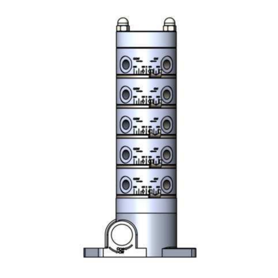
3.2 OCL-M Pump design 3. Overview, functional Fig. 2 description 3.1 Main components of OCL-M Fig. 1 Pump ring assembly in pressure phase Legend of Figure 2: 1 Gear box assembly 2 Oil inlet (lubricant inlet / pump inlet) plate 3 Pump ring assembly 4 Pump shaft 5 Radial pistons... -
Page 13: Pump Ring Assembly
connects the space between two radial pistons with a lubricant 3.5 Gear box assembly inlet in the pump ring. This is the suction phase. Below are the gear box variants available for the OCL-M Pump As the pump shaft continues to rotate, due to the elliptically (refer Table 4 for details). - Page 14 Drive shaft on the pump gear box is coupled to the superior NOTE machine’s drive shaft. Based on the direction of drive rotation • The individual pump ring can be set to not less (1) (CW or CCW), user can vary the pump output from MAX to than 1/3 capacity MIN by adjusting the holding disc (5) position on the pump ring •...
-
Page 15: Technical Data
4. Technical data Table 5 General Technical Data Parameter Value Mounting position Weight of pump ~1 Kg (with 1 pump ring) ~1.3 Kg (with 2 pump rings) ~1.6 Kg (with 3 pump rings) ~1.9 Kg (with 4 pump rings) ~2.2 Kg (with 5 pump rings) Type Radial piston pump Max. -
Page 16: Tightening Torques
4.1 Tightening torques Fig. 6 Table 6 Tightening torques Reference Part Tightening torques Pump mounting holes 5 Nm ± 1.0 Nm 3.688 ft.lb ± 0.74 ft.lb Dome nut 3 Nm ± 1.0 Nm 2.212 ft.lb ± 0.74 ft.lb Screw rod 5 Nm ±... -
Page 17: Type Identification Code Ocl-M
4.2 Type identification code OCL-M O C L - M - G 1 - 1 7 - 0 6 - 0 4 Type designation/type of actuation: Oil Chain Lubrication Pump Drive/operation mode: Mechanical operated Gear box 1 : 6.75 1 : 27 Number of Pump ring Ø... - Page 18 Table 7 Examples of OCL-M pump configurations Type identification code Description No. of pump Pump picture rings OCL-M-G1-14 OCL-M pump with 1:6.75 gear box and 1 pump ring Ø 4 mm OCL-M-G1-17-16 OCL-M pump with 1:6.75 gear box and 1 pump ring Ø...
-
Page 19: Selection Of The Pump
4.3 Selection of the pump 1. For the pump selection, user must check the equipment drive speed (RPM) of the equipment (preferably from the equipment user manual) and output range (Min to Max) required for the application 2. User must refer charts in figure 7 through figure 12 and then select the pump ring type and gear box type based on the application requirement Fig. - Page 20 Fig. 8 Flow rate chart for pump ring D4 with gear ratio 1:6.75 Fig. 9 Flow rate chart for pump ring D6 with gear ratio 1:27...
- Page 21 Fig. 10 Flow rate chart for pump ring D6 with gear ratio 1:6.75 Fig. 11 Flow rate chart for pump ring D7 with gear ratio 1:27...
-
Page 22: Example Of Selecting A Pump Ring And Gear Box Types Based On Application
Fig. 12 Flow rate chart for pump ring D7 with gear ratio 1:6.75 4.3.1 Example of selecting a pump ring and gear box types based on application Fig. 13 Maximum setting Minimum setting Example of pump selection... -
Page 23: Flow V/S Viscosity Of Oil
Refer figure 13 If the drive shaft speed (input RPM) is 550 RPM and if the minimum required output 0.15 cc/outlet and maximum required output 0.4 cc/outlet, then: 1. Locate the input RPM on the X Axis at 550 RPM 2. -
Page 24: Delivery, Returns, Storage
5. Delivery, returns, storage 5.1 Delivery After receipt of the shipment, it must be inspected for any shipping damage and for completeness according to the shipping documents. Immediately inform the transport carrier of any shipping damage. The packaging material must be preserved until any discrepancies are resolved. -
Page 25: Assembly
6. Assembly Ensure to perform below steps before doing the system installation. 6.1 Preparation for Installation 1. Ensure all components are received correctly as per the packing list provided. 2. Ensure all required tools are in place. 6.2 Plan for Installation 1. -
Page 26: Installation And Mounting Of Ocl-M Pump
Fig. 17 Installation dimensions (top view) Table 8 Installation dimensions Gear ratio Number of pump rings * Dimension (A) Number of outlets 1:6.75 1:27 107 mm 1:6.75 1:27 134 mm 1:6.75 1:27 161 mm 1:6.75 1:27 188 mm 1:6.75 1:27 215 mm * Dimensions in table 8 are same for D4, D6 and D7 pump rings 6.4 Installation and mounting of OCL-M pump... -
Page 27: Equipment Drive Shaft End Connection
CAUTION High pressure pump outlets Risk of injury due to pump outlet pressure • Pressure at the closed outlet can reach up to 80 bar. Do not open the closure plugs when the pump is in operation. • Always follow safety precautions and depressurize the system before approaching near the closed outlets of the pump Pump mounting is carried out at the mounting holes M (Fig. -
Page 28: Installation Of Reservoir
CAUTION Risk of hand crushing Hand injury or crushing may occur due to the rotating drive shaft assembly Rotation of pump drive is permitted only when the equipment cover is closed. Don’t reach into the rotating drive shaft assembly area during operation CAUTION Risk of objects hitting... -
Page 29: Connection Of Main Lubrication Lines (Reservoir With Pump)
Fig. 20 Reservoir mounting on the machine 6.7 Connection of main lubrication lines (reservoir with pump) 1. Plan the routing of the lubrication inlet line between reservoir and OCL-M pump and suitably cut the hose to the required length 2. Assemble the barb fitting (Fig. 21/5) into the pump inlet 3. -
Page 30: Installation Of Brushes
6.8 Installation of Brushes NOTE • When using brushes or felt strips ensure even distribution of the lubricant volume on the entire width of the chain. • Assemble the brush or felt strip on the brush mounting bracket to ensure positive engagement of brushes to the chain or lube point. -
Page 31: Pump Outlet Ports Configurations
6.10 Pump outlet ports configurations 1. Pump outlet ports can be combined to get the desired output by using a Y-connector (Fig. 23/2). 2. Figure 23 shows the following options of combining outlets using a Y-connector: • Pump outlet P (Fig. 23/1) can be split into two outputs Q and R, can be connected to two brush inlets (feeder lines) •... -
Page 32: Initial Priming And Pre-Start Procedure
1. Pump is delivered without pre-filling of lubricants 2. Fill the reservoir with appropriate chain oil (recommended by SKF) up to the MAX level marking on the reservoir 3. Drive the pump manually with a battery screwdriver until the oil is sucked from the reservoir, fills the pump and reaches the brush inlets through the feeder lines 4. -
Page 33: General Instructions: Lubrication Line Connection
• Install lubricant metering devices at the end of the main 6.14 General Instructions: Lubrication lubricant line such that the outlets of the lubricant metering line connection devices point upwards wherever possible. • If the system configuration requires that the lubricant <... -
Page 34: First Start-Up
7. First start-up In order to warrant safety and proper functioning of the system, a person assigned by the operator must carry out the following inspections before start-up. Immediately eliminate detected deficiencies, if found. Deficiencies may be remedied by an authorized and qualified specialist only. -
Page 35: Operation
8. Operation NOTICE SKF products operate automatically to the greatest possible Fill bubble free lubricant extent. Always fill the reservoir with clean and bubble free During operation the following notes should be observed to (air free) lubricant up to the MAX marking only. - Page 36 Fig. 27 Drain the reservoir...
-
Page 37: Maintenance And Repair
9. Maintenance and repair 9.1 Maintenance Regular and appropriate maintenance is a prerequisite to detect and clear faults in time. The specific timelines have to be determined, verified at regular intervals and adapted by the operator based on the operating conditions. If needed, use the below table for regular maintenance activities. -
Page 38: Cleaning
10. Cleaning 10.1 Basics Cleaning should be carried out in accordance with the operator's own company rules, and cleaning agents and devices and the personal protective equipment to be used should likewise be selected in accordance with those rules. Only cleaning agents compatible with the materials may be used for cleaning. -
Page 39: Faults, Causes, And Remedies
• Defective pump ring • Check and replace pump ring, if necessary • Dirt in releif valve • Contact SKF customer support Excessive lubrication • Wrong metering volume • Check output volume (see chapters 4. Technical data and 4.3 Selection of the pump) •... -
Page 40: Repairs
12. Repairs < WARNING Risk of injury At a minimum, the following safety measures must be taken before any repairs: • Unauthorized persons must be kept away • Mark and secure the work area • Use personal protective equipment as necessary •... -
Page 41: Spare Parts
14. Spare parts Spare parts may be used exclusively for replacement of identical defective parts. Modifications with spare parts on existing products are not allowed. 14.1 Spare parts for OCL-M kit Table 13 OCL-M pump mounting bracket set Spare part no. Description Quantity Image... - Page 42 Table 16 Brush assembly D9 set Spare part no. Description Quantity Image 6770-02505-3 Brush assembly D9 set Table 17 Brush assembly D25 set Spare part no. Description Quantity Image 6770-02506-3 Brush assembly D25 set Table 18 Brush D9 mounting plate set Spare part no.
- Page 43 Table 19 OCL-M pump drive shaft connecting set Spare part no. Description Quantity Image 6770-02501-3 OCL-M pump drive shaft connecting set Table 20 Flexible tube helix 3/8” black Spare part no. Description Quantity Image 6770-02509-4 Flexible tube helix 3/8” black (25 meters) Table 21 Flexible tube conduit 3/8”...
-
Page 44: Details Of Adapters -Threaded And Welded
Table 23 Y-Connector set Spare part no. Description Quantity Image 6770-02513-4 Y-Connector set 14.2 Details of Adapters -threaded and welded Fig. 28 Adapter Threaded... - Page 45 Fig. 29 Adapter Welded...
- Page 46 ® SKF and Lincoln are registered trademarks of the SKF Group. ™ eLube is a trademark of the SKF Group. © SKF Group 2023 Reprint or reproduction of the contents of this information - even in part - is permitted only with SKF's prior written consent.
Need help?
Do you have a question about the Lincoln OCL-M-G Series and is the answer not in the manual?
Questions and answers