SKF LINCOLN P203 Assembly Instructions Manual
Lubricant pump for multi-line lubrication systems
Hide thumbs
Also See for LINCOLN P203:
- Original assembly instructions (88 pages) ,
- Assembly instructions manual (84 pages) ,
- Assembly instructions manual (78 pages)
Table of Contents
Advertisement
Advertisement
Table of Contents

Related Manuals for SKF LINCOLN P203


Summary of Contents for SKF LINCOLN P203
- Page 1 Assembly instructions Lubricant pump P203 following machinery directive 2006/42/EC for multi-line lubrication systems AC versions without PCB LINCOLN LINCOLN LINCOLN LINCOLN LINCOLN 951-171-020-EN Version 01 28/03/2018 P203 AC wo PCB 951-171-020-EN-V01.indd 1 09.01.2019 10:56:00...
-
Page 2: Ec Declaration Of Incorporation Acc. To Machinery Directive 2006/42/Ec
EC Declaration of incorporation EC Declaration of incorporation acc. to machinery directive 2006/42/EC The manufacturer, SKF Lubrication Systems Germany GmbH, Walldorf Facilities, Heinrich-Hertz-Str. 2-8, DE - 69190 Walldorf, hereby declares that the partly completed machinery Designation: Electrically driven pump to supply lubricant during intermittent operation within a centralized lubrication system... -
Page 3: Legal Disclosure
○ Intent or negligence Warranty Berlin Facilities The instructions do not contain any informa- ○ use of non-original SKF spare parts Motzener Straße 35/37 tion on the warranty. This can be found in ○ Faulty planning or layout of the central- 12277 Berlin our general terms and conditions. -
Page 4: Table Of Contents
Table of contents Table of contents EC Declaration of incorporation acc. to machinery directive 2006/42/EC ..2 Legal disclosure ...................... 3 Explanation of symbols, signs and abbreviations ..........7 Safety instructions .................9 Lubricants ................... 17 General safety instructions ..............9 General information ................17 General behaviour when handling the product ........ - Page 5 Table of contents Useable reservoir volume ..............32 Filling with lubricant ................52 4.10 Lubricant requirement for priming of an empty pump ....33 6.8.1 Filling via the reservoir lid ..............52 4.11 Tightening torques ................34 6.8.2 Filling via filler fitting ................53 4.12 Type identification code ................35 6.8.3 Filling via the optional filling connection ..........54 Delivery, returns, and storage ............
- Page 6 Table of contents Repairs ..................61 14.7 Adapter with lubrication fitting ............65 12.1 Check pump element and replace pressure control valve....61 14.8 Closure screw M22 x 1,5..............65 14.9 Transparent reservoir ................66 Shutdown and disposal ............... 62 14.10 Fixed paddle ..................67 13.1 Temporary shutdown ................62 14.11...
-
Page 7: Explanation Of Symbols, Signs And Abbreviations
Explanation of symbols, signs and abbreviations Explanation of symbols, signs and abbreviations The following abbreviations may be used within these instructions. Symbols within safety notes mark the kind and source of the hazard. General warning Dangerous electrical voltage Risk of falling Hot surfaces Unintentional intake Crushing hazard... - Page 8 Explanation of symbols, signs and abbreviations Abbreviations and conversion factors regarding °C degrees Celsius °F degrees Fahrenheit approx. approximately Kelvin ounce i.e. that is Newton fl. oz. fluid ounce poss. possibly hour inch if appl. if applicable second pounds per square inch incl.
-
Page 9: Safety Instructions
1. Safety instructions 1. Safety instructions 1.1 General safety instructions 1.2 General behaviour when handling the product ○ The owner must ensure that safety infor- ○ Responsibilities for different activities ○ The product may be used only in aware- mation has been read by any persons en- trusted with works on the product or by ness of the potential dangers, in proper must be clearly defined and observed. -
Page 10: Intended Use
1. Safety instructions 1.3 Intended use 1.6 Prohibition of certain activities ○ to supply, transport, or store hazardous Supply of lubricants within a centralized lu- Due to potential sources of faults that may substances and mixtures in accordance brication system following the specifications, not be visible or due to legal regulations with annex I part 2-5 of the CLP regula- technical data and limits stated in these... -
Page 11: Notes Related To The Ce Marking
1. Safety instructions 1.8 Notes related to the CE marking 1.9 Inspections prior to delivery CE marking is effected following the require- The following inspections were carried out ments of the applied directives: prior to delivery: ○ 2014/30/EU ○ Safety and functional tests Electromagnetic compatibility ○... -
Page 12: Markings On The Product
1. Safety instructions 1.12 Notes related to the type identiica- 1.11 Markings on the product SKF Lubrication Systems Germany GmbH tion plate Model: P203-xxxxx-xxx-xx P. No.: 644-xxxxx-x S. No.: xxxxxxxxxxxx The type identification plate states important characteristics such as type designation, or-... -
Page 13: Persons Authorized To Operate The Pump
1. Safety instructions 1.14 Brieing of external technicians 1.13 Persons authorized to operate the 1.16 Operation pump The following must be observed during com- Prior to commencing the activities, external missioning and operation: technicians must be informed by the opera- 1.13.1 Operator tor of the company safety provisions, the ○... -
Page 14: Transport, Installation, Maintenance, Malfunctions, Repair, Shutdown, Disposal
1. Safety instructions 1.18 Transport, installation, maintenance, ○ Ensure through suitable measures that ○ Carry out electrical connections only ac- malfunctions, repair, shutdown, movable or detached parts are immobi- cording to the information in the valid disposal lized during the work and that no limbs wiring diagram and taking the relevant ○... -
Page 15: Initial Commissioning / Daily Start-Up
1. Safety instructions 1.19 Initial commissioning / daily start-up 1.20 Cleaning ○ Risk of fire and explosion when using ○ All components used must be designed Ensure that: inflammable cleaning agents Only use ○ All safety devices are completely available according to the maximum operating non-flammable cleaning agents suitable pressure and the maximum respectively... -
Page 16: Residual Risks
1. Safety instructions 1.21 Residual risks Residual risk Possible in life cycle Prevention/ remedy Personal injury/ material damage due to Keep unauthorized persons away No people may remain under suspended loads. Lift A B C G H K falling of raised parts parts with adequate lifting devices. -
Page 17: Lubricants
2.2 Selection of lubricants 2.3 Material compatibility Lubricants are used specifically for cer- SKF considers lubricants to be an element Lubricants must generally be compatible tain application purposes. In order to fulfil of system design. A suitable lubricant is se-... -
Page 18: Ageing Of Lubricants
(e.g. "bleeding"). hazard designations, if any, on the packaging have to be Please contact SKF. if you have further ques- observed. tions regarding lubricants. You may request an overview of the lubri- cants tested by SKF. -
Page 19: Chisel Pastes
NOTICE Chisel pastes containing calcium carbonate Solid lubricants may be used only are likely to cause a very strong wear on pis- upon prior consultation of SKF Damage to the superior machine tons, bores and mating surfaces. Lubrications Systems. Chisel pastes must not be used as a lubri- Calcium hydroxide cant for bearings. -
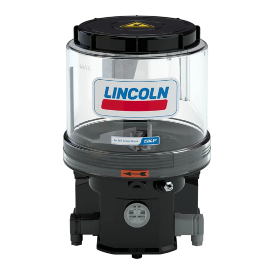
Page 20: Overview, Functional Description
3. Overview, functional description 3. Overview, functional description Overview, functional description of pumps without follower plate Fig. 1 3.1 Pumps without follower plate 1 Reservoir The lubricant is stored in the reservoir. De- pending on the pump version there are differ- ent types of reservoirs and reservoir sizes. - Page 21 3. Overview, functional description Overview, functional description of pumps without follower plate Fig. 2 2 Pump housing The pump housing accommodates the motor, Type of connection the electrical connections, the filler fitting and the pump elements. Square plug 3 pump elements The pump can be equipped with up to 3 pump elements (see chapter 4.9).
-
Page 22: Pumps With Follower Plate
3. Overview, functional description Overview, functional description of pumps with follower plate Fig. 3 3.2 Pumps with follower plate 1 Reservoir The lubricant is stored in the reservoir. De- pending on the pump version there are differ- ent types of reservoirs and reservoir sizes. 1.2 Reservoir venting device It provides air for the reservoir while the pump is operating and lubricant is supplied. - Page 23 3. Overview, functional description Overview, functional description of pumps with follower plate Fig. 4 2 Pump housing The pump housing accommodates the motor, Type of connection the electrical connections, the filler fitting and the pump elements. Square plug 3 pump elements The pump can be equipped with up to 3 pump elements.
-
Page 24: Technical Data
4. Technical data 4. Technical data 4.1 General technical data Operating pressure max. 350 bar [5076 psi] Rated voltage 110 - 260 V AC (± 10 %) Number of pump elements max. 3 Frequency 50-60 Hz (± 5 %) | 1-phase Direction of rotation clockwise Recommended back-up fuse... -
Page 25: Protection Type And Class
4. Technical data 4.2 Protection type and class 4.3 Hydraulic connection diagram 1 = Reservoir Degree of protection IP6K9K Protection classes 2 = Pump Connection nominal voltage Protection class 1 3 = Check valve Connection signal line Protection class 3 4 = Pressure control valve - Square plug SELV / PELV / FELV... -
Page 26: Nominal Output Volumes
4. Technical data 4.4 Nominal output volumes The stated nominal outputs per stroke and pump element refer to NLGI 2 lubrication greases at an ambient temperature of + 20 °C [68 °F] and a back pressure of 100 bar [1450 psi] on the pump element. Deviating operating conditions or deviating pump configuration result in a changed motor speed and thus in a change of the output per time unit. -
Page 27: Output Diagrams Of Typical Nlgi 2 Lubricants
4. Technical data 4.4.2 Output diagrams of typical NLGI 2 lubricants Low temperature lubrication grease High temperature lubrication grease °C °C 86 104 122 °F 86 104 122 °F The output diagrams represent the average value of the different high- respectively low-temperature lubrication greases. Calculation of the output using the example of a high-temperature lubrication grease Nominal speed of the pump motor per minute x nominal output of pump element 7 per stroke x efficiency in percent at an assumed ambient temperature of -10 °C [14 °F] = 20 rpm x 0.22 cc (0.0134) x 80 % = 3.5 cc/min [0.214 cu.in./min.]. -
Page 28: Functioning Principle Of The Intermittent Low-Level Indication
4. Technical data 4.5 Functioning principle of the intermittent low-level indication The intermittent low-level indication operates free of contact. Its main components are the following: ○ firmly positioned magnetic switch (I) inside of the reservoir bottom ○ flexible guide plate (II) connected to the stirring paddle with a magnet (III) and a control cam (IV) If the reservoir is filled with a lubrication grease suitable for the intermittent low-level indication and the pump is operating, then the guide plate (II) is de- flected by the resistance of the lubrication grease. -
Page 29: Limits Of Use Of The Intermittent Low-Level Indication
4. Technical data 4.6 Limits of use of the intermittent low-level indication The following lubricant consistencies have to be complied with in order to ensure the correct functioning of the intermittent low-level indication. Above the stated range of temperature a correct functioning of the intermittent low-level indication cannot be ensured. The inferior temperature ranges require the suitability of the lubricant for the respective temperature range. -
Page 30: Processing Of The Low-Level Signals In Case Of External Controller And Monitoring Of The Pump
4. Technical data 4.7 Processing of the low-level signals in case of external controller and monitoring of the pump The following statements apply to pumps with control printed circuit board type V and for pumps without printed circuit board with external controller and monitoring. -
Page 31: Reservoir Versions
4. Technical data 4.8 Reservoir versions In the following you find the possible reservoir variants of the pumps described in these instructions (also see type identification code). For a better representation only the smallest possible reservoir size will be depicted always. In the figures the different reservoir variants may not ü... -
Page 32: Useable Reservoir Volume
4. Technical data 4.9 Useable reservoir volume Regarding the reservoir version without follower plate the useable reservoir volume mainly depends on the NLGI consistency class of the lubricant to be used and of the ambient temperature. In case of high consistency and low operating temperature normally more lubricant sticks to the inner surfaces of the reservoir and the pump and is thus no more available for being dispensed. -
Page 33: Lubricant Requirement For Priming Of An Empty Pump
4. Technical data 4.10 Lubricant requirement for priming of an empty pump To prime an empty pump up to the MAX marking of the reservoir, the following lubricant quantities are required. Nominal volume | Litres / [gal.] 2 [0.53] 4 [1.06] 8 [2.11] 11 [2.90] 15 [3.96]... -
Page 34: Tightening Torques
4. Technical data 4.11 Tightening torques A Pump element 20 Nm ± 2,0 Nm [14.75 ft.lb. ± 1.4 ft.lb.] B Pressure control valve 6 Nm -0,5 Nm [4.43 ft.lb. - 0.07 ft.lb.] C Pump 18 Nm ± 1.0 Nm [13.27 ft.lb. ± 0.74 ft.lb.] D Screw cap 2 Nm ±... -
Page 35: Type Identification Code
4. Technical data 4.12 Type identiication code The type identification code facilitates selection/ identification of important features of the product. For the type identification code of the respective prod- uct, see the type identification plate on the pump. P 2 0 3 X U - 1 1 X L B 0 - 6 0 0 - A C - D 1 0 0 G 2 0 0 - _ _ _ A + _ _ _ Example H K H K H K H K Category 1 2 3... - Page 36 4. Technical data P 2 0 3 X D - 1 1 X L B 0 - 6 0 0 - A C - D 1 0 0 G 2 0 0 - _ _ _ A + _ _ _ Example H K H K H K H K Category 1 2 3...
- Page 37 4. Technical data P 2 0 3 X D - 1 1 X L B 0 - 6 0 0 - A C - D 1 0 0 G 2 0 0 - _ _ _ A + _ _ _ Example H K H K H K H K Category 1 2 3...
- Page 38 4. Technical data P 2 0 3 X D - 1 1 X L B 0 - 6 0 0 - A C - D 1 0 0 G 2 0 0 - _ _ _ A + _ _ _ Example H K H K H K H K Category 1 2 3...
-
Page 39: Delivery, Returns, And Storage
5.3 Storage 5.4 Storage temperature range ○ In case of parts not filled with lubricant After receipt of the shipment, check the SKF products are subject to the following shipment for damage and completeness storage conditions: the admissible storage temperature according to the shipping documents. -
Page 40: Storage Conditions For Parts Filled With Lubricant
5. Delivery, returns, and storage 5.5 Storage conditions for parts illed 5.5.3 Storage period exceeding 18 Metering devices with lubricant months • Remove all connection lines and closure To avoid dysfunctions consult the manufac- The conditions mentioned in the follow- screws, if any turer before commissioning. -
Page 41: Installation
6. Installation 6. Installation 6.2 Place of installation 6.1 General information ○ Possibly existing visual monitoring de- Protect the product against humidity, dust Only qualified technical personnel may install vices, e.g. pressure gauges, MIN/MAX and vibrations and install it in an easily ac- the products described in these Instructions. -
Page 42: Mechanical Connection
6. Installation 6.3 Mechanical connection 6.3.1 Minimum assembly dimensions Ensure sufficient space for maintenance work or for attachment of further components to build a centralized lubrication system to the pump by leaving a free space of at least 100 mm [3.94 in.] into each direction in addition to the stated dimensions. Reservoir Reservoir size Reservoir size... - Page 43 6. Installation Reservoir Reservoir size Reservoir size Reservoir size version ~ Height (H) mm [in.] ~ Width (B) mm [in.] ~ Depth (T) mm [in.] Litres gal. [0.53] [1.06] [2.11] [2.90] [3.96] [0.53] [1.06] [2.11] [2.90] [3.96] [0.53] [1.06] [2.11] [2.90] [3.96] XCBO...
- Page 44 6. Installation Minimum assembly dimensions Fig. 5 LINCOLN LINCOLN LINCOLN LINCOLN LINCOLN 951-171-020 - 44 - Version 01 P203 AC wo PCB 951-171-020-EN-V01.indd 44 09.01.2019 10:56:14...
-
Page 45: Installation Bores
6. Installation 6.3.2 Installation bores Pumps with 8 l [2.11 gal.] reservoir Pumps with 2 l [0.53gal.] or 4 l [1.06 gal.] reservoir Are fixed at the three lower fastening points NOTICE (A) or (B) and (C) of the pump housing. Are fixed at the two lower fastening points (A) or (B) of the pump housing. - Page 46 6. Installation Pumps with 11 l [2.9 gal.] or 15 l [3.96 gal.] Mounting bores for pumps with 11 l [2.9 gal.] or 15 l [3.96 gal.] reservoir Fig. 7 reservoir Are fixed on the lower mounting bores (A) or (B) of the pump housing and additionally on the 2 upper mounting points (D).
-
Page 47: Electrical Connection
6. Installation 6.4 Electrical connection Electrical connection, Fig. 8 Type of connection WARNING Square plug Electric shock Make sure to disconnect the product from the power supply before carrying out any works on electrical components. Carry out the electrical connection accor- ding to the connection type of the pump, •... - Page 48 6. Installation Electrical connection of the low-level indication of pumps with follower plate Fig. 9 The electrical connection of the low-level indication (5.3) of pumps with follower plate is made according to the pump’s connection type. See chapter Connection of the signal line to the reservoir lid 951-171-020 - 48 - Version 01...
-
Page 49: Adjusting The Output Volume On The Pump Element R
6. Installation 6.5 Adjusting the output volume on the Adjusting the output volume on pump element R Fig. 10 pump element R The output of pump element [0.0061] 0,18 R can be adjusted only while the pump is idle. Factory [0.0054] 0,16 setting is full supply, i.e. -
Page 50: Mount Pressure Control Valve
6. Installation 6.6 Mount pressure control valve Mounting the pressure control valve Fig. 11 Protect each pump element by means of a pressure control valve suitable for the planned maximum admissible operating pressure of the centralized lubrication system. Observe the information given in chapter 4 regarding the adapter required for certain reservoir sizes. -
Page 51: Lubrication Line Connection
6. Installation 6.7 Lubrication line connection ○ The lubricant flow should not be impeded Observe the following installation instruc- CAUTION by the installation of sharp elbows, angle tions for safe and smooth operation. valves, gaskets protruding to the inside, ○ Use clean components and filled lubrica- Risk of falling or cross-section changes (big to small). -
Page 52: Filling With Lubricant
6. Installation Filling via the reservoir lid Fig. 12 6.8 Filling with lubricant 6.8.1 Filling via the reservoir lid WARNING Crushing hazard on the rotating stirring paddle. Fill- ing via the reservoir lid is allowed only after disconnecting the pump from the power supply by removing it from the connection (5.1). -
Page 53: Filling Via Filler Fitting
6. Installation 6.8.2 Filling via iller itting Filling via filler fitting Fig. 13 • Connect filling connection of filler pump with filler fitting (4). • Switch on filler pump and fill reservoir until shortly below the MAX marking • Switch filler pump off and remove it from filler fitting (4) of pump 951-171-020 Version 01... -
Page 54: Filling Via The Optional Filling Connection
6. Installation 6.8.3 Filling via the optional illing Filling with lubricant via filling connection Fig. 14 connection • Unscrew protective cap (20.1) from fill- ing connection (20) anticlockwise • Connect filling connection of filler pump with filler fitting (20) • Switch on filler pump and fill reservoir until shortly below the MAX marking •... -
Page 55: Initial Start-Up
7. Initial start-up 7. Initial start-up In order to warrant safety and function, a person assigned by the operator must carry out the following inspections. Immediately eliminate detected deficiencies. Deficiencies may be remedied by an authorized and qualified specialist only. Start-up check list 7.1 Inspections prior to initial start-up Electrical connection carried out correctly. -
Page 56: Operation
8. Operation 8. Operation SKF products operate automatically to the greatest possible extent. Basically, activities during standard opera- tion are limited to the control of the filling level of pumps without low-level indication and the timely refilling of lubricant. 8.1 Reill lubricant... -
Page 57: Cleaning
• Thorough cleaning of all outer surfaces uct will be required. Thoroughly remove residues with a damp cloth. To do so, contact the SKF Customer Service. of cleaning agents from the product and rinse off with clear Make sure to keep the reser- water. -
Page 58: Maintenance
10. Maintenance Maintenance Regular and appropriate maintenance is a prerequisite to detect and clear faults in time. The specific timelines have to be determined, verified at regular intervals and adapted, if necessary, by the operator based on the operating conditions. If needed, copy the table for regular mainte- nance activities. -
Page 59: Troubleshooting
11. Troubleshooting Troubleshooting Fault table 1 Fault Possible cause Remedy Pump does not run Power supply to pump interrupted Check whether one of the indicated faults is present and rem- edy it in the frame of responsibilities. - Superior machine is switched off - Connection cable of pump is loose or defective Faults outside of your own responsibility have to be reported to your superior to initiate further measures. - Page 60 11. Troubleshooting Fault table 2 Fault Possible cause Remedy Blockade, fault within the centralized lubrication system Defective check valve Defective pressure relief valve Suction bore of pump element is clogged Check whether one of the indicated faults is present and rem- edy it in the frame of responsibilities.
-
Page 61: Repairs
12. Repairs Repairs 12.1 Check pump element and replace Replace pump element Fig. 15 WARNING pressure control valve. Risk of injury The characteristics of the new Before carrying out any repair work, pump element must correspond take at least the following safety to the characteristics of the pump measures: element to be replaced. -
Page 62: Shutdown And Disposal
13. Shutdown and disposal Shutdown and disposal 13.1 Temporary shutdown 13.3 Disposal Countries outside the European Union Temporarily shut the system down by: Countries within the European Union The disposal has to be done according to the ○ Switching off the superior machine. Disposal should be avoided or minimized valid national regulations and laws of the wherever possible. -
Page 63: Spare Parts
14. Spare parts Spare parts The spare parts assemblies may be used exclusively for replacement of identical defective parts. Modifications with spare parts on existing products are not allowed. Exceptions to this are the pump elements and the optional filling connection. 14.1 Housing cover assy. -
Page 64: Pressure Control Valve And Adapter
14. Spare parts 14.3 Pressure control valve and adapter Fig. 18 Designation Qty. Part number Pressure control valve SVTS-350-R 1/4-D6 | C3 624-28894-1 Pressure control valve SVTS-350-R 1/4-D6 | C5-M 624-29343-1 Pressure control valve SVET-350-G 1/4 A-D8 | C3 624-29054-1 Pressure control valve SVTSV-270-R1/4-1/8NPTFI-NIP00R-A | C3 270864 Adapter S2520 1/4 -1/4 with PTFE sealing... -
Page 65: Magnetic Switch Normally Open (No)
14. Spare parts 14.6 Magnetic switch normally open (NO) Fig. 21 Designation Qty. Part number Magnetic switch normally open (NO) for intermittent low-level indication 544-60276-1 Delivering including housing cover, drain hose, and the corresponding number of screws required for installation 14.7 Adapter with lubrication itting Fig. -
Page 66: Transparent Reservoir
8 l XNBO/ YNBO/ XLBO/ YLBO/ XBF A,B,C 544-31999-1 -MIN- -MIN- 8 l XN/ XL A,B,C,D 544-32696-1 Delivery including: A = Lincoln/SKF Logo; B = Directional arrow; C= O-ring; D = Reservoir lid; E = 544-31998-1 544-32695-1 Warning label ‘Crushing hazard’ -MAX- -MAX- LINCOLN LINCOLN... -
Page 67: Fixed Paddle
14. Spare parts 14.10 Fixed paddle Fig. 25 Designation Qty. Part number Fixed paddle 4 XNBO 444-70490-1 Fixed paddle 8 XNBO 444-70491-1 14.11 Reservoir lid Fig. 26 Designation Qty. Part number A) Reservoir lid 4/8l [1.06/2.11 gal.] XNBA/XLBA 544-36963-1 B) Reservoir lid 4/8l [1.06/2.11gal.] 544-31992-1 A) Lockable including 2 keys and warning label B) Including warning label... -
Page 68: Connection Sockets And Cable
14. Spare parts 14.13 Connection sockets and cable Feature* Qty. Part number Designation Fig. 28 Connection socket with gasket and screw 544-32850-1 Connection socket with gasket and screw 544-33843-1 Connection cable 10 m (33 ft) with connection socket 664-36078-7 Connection cable 10 m (33 ft) with connection socket 664-36078-9 *Feature in type identification code (category K connection material) H) = black... -
Page 69: Replacement Kit P203 Ac Pumps
14. Spare parts 14.14 Replacement kit P203 AC pumps Fig. 29 Designation Qty. Part number Replacement kit of power supply board 544-60043-1 +24Vdc 0Vdc Delivering including housing cover, drain hose, and the corresponding number of screws required for installation 951-171-020 Version 01 - 69 - P203 AC wo PCB 951-171-020-EN-V01.indd 69... -
Page 70: Electrical Connections
15. Connection diagrams Electrical connections 15.1 Cable colours following IEC 60757 Abbreviation Colour Abbreviation Colour Abbreviation Colour Abbreviation Colour black green white pink brown yellow orange turquoise blue violet ----- ----- The assignment of the following electrical connection diagrams is done according to the respective referenced type identification code characteris- tics. -
Page 71: Connection Of Signal Line To Reservoir Lid
15. Connection diagrams 15.2 Connection of signal line to reservoir lid Connection of the signal with the square plug to reservoir lid Fig. 30 Connection diagram (lubrication grease) Connection diagram (lubrication grease) Connection diagram (lubricating oil) Magnetic switch Low-level indication Magnetic switch high- and low-level indication Float magnetic switch Low-level indication Depiction of unactuated condition... -
Page 72: Recommended Contact Protection Measure For Switching Inductive Loads
15. Connection diagrams 15.3 Recommended contact protection measure for switching inductive loads Recommended contact protection measure for switching inductive loads Fig. 31 For protection of the relay contacts the following contact protection measure should be carried out by the operator. V DC 1 Magnetic switch 2 Interference suppression diode... -
Page 73: Connection Diagram P203 V Ac Without Control Pcb
15. Connection diagrams 15.4 Connection diagram P203 V AC without control PCB Connection diagram P203 V AC without control PCB Fig. 32 P203 804-51098-1 Page 1/1 L1 Low-level indication High-level indication Low-level indication L3 Prewarning empty High-level indication 24V Motor 3 2 1 0 No connection D Square plug - power supply plate/supply line... - Page 74 Notes P203 AC wo PCB 951-171-020-EN-V01.indd 74 09.01.2019 10:56:30...
- Page 75 Notes P203 AC wo PCB 951-171-020-EN-V01.indd 75 09.01.2019 10:56:30...
- Page 76 Notes P203 AC wo PCB 951-171-020-EN-V01.indd 76 09.01.2019 10:56:30...
- Page 77 SKF Lubrication Systems Germany GmbH Walldorf Facilities Heinrich-Hertz-Str. 2-8 DE - 69190 Walldorf Phone: +49 (0) 6227 33-0 Fax: +49 (0) 6227 33-259 e-mail: Lubrication-germany@skf.com www.skf.com/lubrication 951-171-020-EN Version 01 28/03/2018 P203 AC wo PCB 951-171-020-EN-V01.indd 77 09.01.2019 10:56:30...
Need help?
Do you have a question about the LINCOLN P203 and is the answer not in the manual?
Questions and answers